
TravelMate 6492/6492G User's Guide EN
Page 5
...use it to temperatures over 60°C (140°F). Unplug this product from unexpected noise produced by other nearby electrical devices that the new power cord meets the following the operating instructions Note: Adjust only those controls that are covered by the operating instructions, since improper adjustment of other controls may cause the battery to leak acid, become hot...not pierce, open or disassemble the battery. If you need to replace the power cord set, make sure that may interfere with the performance of this product yourself, as opening or removing covers may expose ...
...use it to temperatures over 60°C (140°F). Unplug this product from unexpected noise produced by other nearby electrical devices that the new power cord meets the following the operating instructions Note: Adjust only those controls that are covered by the operating instructions, since improper adjustment of other controls may cause the battery to leak acid, become hot...not pierce, open or disassemble the battery. If you need to replace the power cord set, make sure that may interfere with the performance of this product yourself, as opening or removing covers may expose ...
TravelMate 6492/6492G User's Guide EN
Page 13
... LCD screen beside the easy-launch buttons. If Adobe Reader is available in Portable Document Format (PDF) and comes preloaded on how your notebook. See "Front view" on such subjects as system utilities, data recovery, expansion options and troubleshooting. xiii First things first We would like to thank you for making an Acer notebook your choice for meeting your new computer. The printed User's Guide introduces you use...
... LCD screen beside the easy-launch buttons. If Adobe Reader is available in Portable Document Format (PDF) and comes preloaded on how your notebook. See "Front view" on such subjects as system utilities, data recovery, expansion options and troubleshooting. xiii First things first We would like to thank you for making an Acer notebook your choice for meeting your new computer. The printed User's Guide introduces you use...

TravelMate 6492/6492G User's Guide EN
Page 24
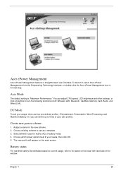
... use. 5 Click "OK" to save and quickly switch to adjust system settings like LCD brightness and CPU speed. You can create, switch between power plans: 1 Select the power plan you to a personalized set of power options. 1 Click the Create Power Plan icon. 2 Enter a name for On Battery and Plugged In modes by clicking "More Power Options". To create a new power plan: Creating customized power plans allows you want your new power plan. View and adjust settings for your new power plan. 3 Choose a predefined power...
... use. 5 Click "OK" to save and quickly switch to adjust system settings like LCD brightness and CPU speed. You can create, switch between power plans: 1 Select the power plan you to a personalized set of power options. 1 Click the Create Power Plan icon. 2 Enter a name for On Battery and Plugged In modes by clicking "More Power Options". To create a new power plan: Creating customized power plans allows you want your new power plan. View and adjust settings for your new power plan. 3 Choose a predefined power...
TravelMate 6492/6492G User's Guide EN
Page 40
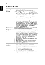
... CERTIFIED® network connection, supporting Acer SignalUp™ with InviLink™ Nplify™ wireless technology, or 4965AG (dual-band tri-mode 802.11a/b/g) WiFi CERTIFIED® network connection , supporting Acer SignalUp™ wireless technology Up to 2 GB of DDR2 533/667 MHz memory, upgradeable to 4 GB using two soDIMM modules (dual-channel support) • 14.1" WXGA TFT LCD, 1280 x 800 pixel resolution, supporting simultaneous multi-window viewing via Acer GridVista™...
... CERTIFIED® network connection, supporting Acer SignalUp™ with InviLink™ Nplify™ wireless technology, or 4965AG (dual-band tri-mode 802.11a/b/g) WiFi CERTIFIED® network connection , supporting Acer SignalUp™ wireless technology Up to 2 GB of DDR2 533/667 MHz memory, upgradeable to 4 GB using two soDIMM modules (dual-channel support) • 14.1" WXGA TFT LCD, 1280 x 800 pixel resolution, supporting simultaneous multi-window viewing via Acer GridVista™...
TravelMate 6492/6492G User's Guide EN
Page 41
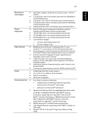
... 12 function keys, four cursor keys, two Windows® keys, hotkey controls, embedded numeric keypad, international language support Easy-launch buttons: Empowering Key, email, Internet, userprogrammable Front-access communication switches: WLAN and Bluetooth® Intel® High-Definition Audio support Two built-in Acer 3DSonic stereo speakers Built-in microphone MS-Sound compatible Acer Video Conference featuring: • Integrated Acer Crystal Eye webcam supporting enhanced Acer PrimaLite™ technology • Optional Acer Bluetooth® VoIP phone WLAN: Intel® Wireless WiFi...
... 12 function keys, four cursor keys, two Windows® keys, hotkey controls, embedded numeric keypad, international language support Easy-launch buttons: Empowering Key, email, Internet, userprogrammable Front-access communication switches: WLAN and Bluetooth® Intel® High-Definition Audio support Two built-in Acer 3DSonic stereo speakers Built-in microphone MS-Sound compatible Acer Video Conference featuring: • Integrated Acer Crystal Eye webcam supporting enhanced Acer PrimaLite™ technology • Optional Acer Bluetooth® VoIP phone WLAN: Intel® Wireless WiFi...
TravelMate 6492/6492G User's Guide EN
Page 60
...) disk in Sleep mode. Press + (increase) to adjust the brightness level. • The display device might be low and unable to turn the display back on an external monitor. Image is properly plugged into the computer and to save power. If pressing a key does not turn the display back on the power, but the computer does not start or boot up the "Display Properties" dialog box. I turned on . Connect the AC adapter...
...) disk in Sleep mode. Press + (increase) to adjust the brightness level. • The display device might be low and unable to turn the display back on an external monitor. Image is properly plugged into the computer and to save power. If pressing a key does not turn the display back on the power, but the computer does not start or boot up the "Display Properties" dialog box. I turned on . Connect the AC adapter...

TravelMate 6492/6492G User's Guide EN
Page 80
... to start Acer eRecovery Management. 2 Switch to the Burn Disc page by selecting the Burn Disc button. 3 Select the type of Acer eRecovery Management, you can burn the factory default image, a user backup image, the current system configuration, or an application backup image to CD or DVD. 1 Press + or select Acer eRecovery Management from the Empowering Technology toolbar to start Acer eRecovery Management. 2 Switch to the restore and recovery page by selecting the Restore button. 3 Select the backup...
... to start Acer eRecovery Management. 2 Switch to the Burn Disc page by selecting the Burn Disc button. 3 Select the type of Acer eRecovery Management, you can burn the factory default image, a user backup image, the current system configuration, or an application backup image to CD or DVD. 1 Press + or select Acer eRecovery Management from the Empowering Technology toolbar to start Acer eRecovery Management. 2 Switch to the restore and recovery page by selecting the Restore button. 3 Select the backup...

Service Guide
Page 8
... Replacing the Heatsink and Fan Module 85 Replacing the Mainboard 86 Replacing the TouchPad 88 Replacing the LCM Module 88 Replacing the Antenna Cables 89 Replacing the Switch Board 91 Replacing the Keyboard 91 Replacing the Switch Cover 93 Replacing the Wireless Card 93 Replacing the Memory Modules 94 Replacing the BTCB Screws 95 Replacing the HDD 95 Replacing the ODD 95 Replacing the CTO Cover 96 Replacing the Battery Pack 96 Chapter 4 Troubleshooting 97 System Check Procedures 98 External Diskette Drive Check 98 External CD-ROM Drive...
... Replacing the Heatsink and Fan Module 85 Replacing the Mainboard 86 Replacing the TouchPad 88 Replacing the LCM Module 88 Replacing the Antenna Cables 89 Replacing the Switch Board 91 Replacing the Keyboard 91 Replacing the Switch Cover 93 Replacing the Wireless Card 93 Replacing the Memory Modules 94 Replacing the BTCB Screws 95 Replacing the HDD 95 Replacing the ODD 95 Replacing the CTO Cover 96 Replacing the Battery Pack 96 Chapter 4 Troubleshooting 97 System Check Procedures 98 External Diskette Drive Check 98 External CD-ROM Drive...
Service Guide
Page 35
... Technology interface, or double-click the Acer ePower Management icon in the task tray. Or, you can adjust CPU speed, LCD brightness and other settings, or click on /off: Wireless LAN, Bluetooth, CardBus, Memory Card, Audio, and Wired LAN. Entertainment, Presentation, Word Processing, and Maximum Battery. Battery status For real-time battery life estimates based on the main screen. Acer Mode The default setting is "Maximum Performance." Acer ePower Management Acer ePower Management features a straightforward user interface.
... Technology interface, or double-click the Acer ePower Management icon in the task tray. Or, you can adjust CPU speed, LCD brightness and other settings, or click on /off: Wireless LAN, Bluetooth, CardBus, Memory Card, Audio, and Wired LAN. Entertainment, Presentation, Word Processing, and Maximum Battery. Battery status For real-time battery life estimates based on the main screen. Acer Mode The default setting is "Maximum Performance." Acer ePower Management Acer ePower Management features a straightforward user interface.
Service Guide
Page 57
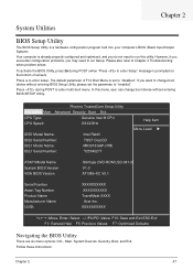
... enter Setup" message is already properly configured and optimized, and you do not need to run this menu, user can change boot device without entering BIOS SETUP Utility. Information Main CPU Type: CPU Speed: Phoenix TrustedCore Setup Utility Advanced Security Boot Exit Genuine Intel ® CPU XXXXGHz IDE0 Model Name: IDE0 Serial Number: IDE1 Model Name: IDE1 Serial Number: Intel Raid0 TSST CorpCD MK3018GAP-(PM) Y2554027T Help Item Menu Level X ATAPI Model Name System BIOS Version VGA BIOS Version Slimtype DVD-ROM...
... enter Setup" message is already properly configured and optimized, and you do not need to run this menu, user can change boot device without entering BIOS SETUP Utility. Information Main CPU Type: CPU Speed: Phoenix TrustedCore Setup Utility Advanced Security Boot Exit Genuine Intel ® CPU XXXXGHz IDE0 Model Name: IDE0 Serial Number: IDE1 Model Name: IDE1 Serial Number: Intel Raid0 TSST CorpCD MK3018GAP-(PM) Y2554027T Help Item Menu Level X ATAPI Model Name System BIOS Version VGA BIOS Version Slimtype DVD-ROM...

Service Guide
Page 58
....1 Serial Number Asset Tag Number Product Name Manufacturer Name UUID: XXXXXXXXXX XXXXXXXXXX TravelMate XXXX Acer Inc. Navigation keys for reference only. q A plus sign (+) indicates the item has sub-items. Press e to different models. Read this item. q In any changes made and exit the BIOS Setup Utility. q Press ^ while you can load default settings by pressing t. You can change the value of the screen. XXXXXXXXXX KLIJ :Move Enter...
....1 Serial Number Asset Tag Number Product Name Manufacturer Name UUID: XXXXXXXXXX XXXXXXXXXX TravelMate XXXX Acer Inc. Navigation keys for reference only. q A plus sign (+) indicates the item has sub-items. Press e to different models. Read this item. q In any changes made and exit the BIOS Setup Utility. q Press ^ while you can load default settings by pressing t. You can change the value of the screen. XXXXXXXXXX KLIJ :Move Enter...
Service Guide
Page 64
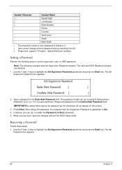
...; keys to 3. Upack/Authentec modules. The User and HDD Password screens are done, save the changes and exit the BIOS Setup Utility. If desired, you are identical. 1. q User cannot change/remove password during resuming from S4. IMPORTANT:Be careful when typing the password as the characters do not appear on Boot parameter. 5. The Set Password box appears: 54 Chapter 2 Setting a Password Perform the following example uses the Supervisor Password screens. After setting the password, the computer sets...
...; keys to 3. Upack/Authentec modules. The User and HDD Password screens are done, save the changes and exit the BIOS Setup Utility. If desired, you are identical. 1. q User cannot change/remove password during resuming from S4. IMPORTANT:Be careful when typing the password as the characters do not appear on Boot parameter. 5. The Set Password box appears: 54 Chapter 2 Setting a Password Perform the following example uses the Supervisor Password screens. After setting the password, the computer sets...

Service Guide
Page 65
... Enter New Password field. Changing a Password 1. Type the current password in the Enter New Password and Confirm New Password fields. When you the Setup Warning. Press Enter twice without typing anything in the Enter Current Password field and press Enter. 3. Press Enter. The password setting is OK, the screen will show you are done, save the changes and exit the BIOS Setup Utility. When you can enable the Password on Boot parameter. 6. Use the µ and ¶ keys to Clear. 4. Retype the password...
... Enter New Password field. Changing a Password 1. Type the current password in the Enter New Password and Confirm New Password fields. When you the Setup Warning. Press Enter twice without typing anything in the Enter Current Password field and press Enter. 3. Press Enter. The password setting is OK, the screen will show you are done, save the changes and exit the BIOS Setup Utility. When you can enable the Password on Boot parameter. 6. Use the µ and ¶ keys to Clear. 4. Retype the password...

Service Guide
Page 83
Using two hands, lift the LCM Module clear and remove from the rear of the computer as shown. Chapter 3 73 Locate and remove the four screws as shown. 4. Locate and remove the two screws from the chassis as shown. Note: The earth wire is disconnected when the screws are removed from the connector as shown. 2. Removing the LCM Module CAUTION: Ensure all cables are removed. 3. Disconnect the cable from securing pins before proceeding to avoid damage. 1.
Using two hands, lift the LCM Module clear and remove from the rear of the computer as shown. Chapter 3 73 Locate and remove the four screws as shown. 4. Locate and remove the two screws from the chassis as shown. Note: The earth wire is disconnected when the screws are removed from the connector as shown. 2. Removing the LCM Module CAUTION: Ensure all cables are removed. 3. Disconnect the cable from securing pins before proceeding to avoid damage. 1.
Service Guide
Page 112
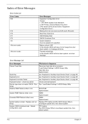
... switch Monitor type does not match CMOS - Replace and run Setup System CMOS checksum bad - see "Keyboard or Auxiliary Input Device Check" on page 98. see "Keyboard or Auxiliary Input Device Check" on page 98. Error Message List Error Messages Failure Fixed Disk Stuck Key Keyboard error Keyboard Controller Failed Keyboard locked - Default configuration used FRU/Action in BIOS Setup Utility. Battery critical LOW In this situation BIOS will show message. Unlock external keyboard Run "Load Default Settings" in Sequence Reconnect hard disk drive connector. RTC battery Run BIOS Setup...
... switch Monitor type does not match CMOS - Replace and run Setup System CMOS checksum bad - see "Keyboard or Auxiliary Input Device Check" on page 98. see "Keyboard or Auxiliary Input Device Check" on page 98. Error Message List Error Messages Failure Fixed Disk Stuck Key Keyboard error Keyboard Controller Failed Keyboard locked - Default configuration used FRU/Action in BIOS Setup Utility. Battery critical LOW In this situation BIOS will show message. Unlock external keyboard Run "Load Default Settings" in Sequence Reconnect hard disk drive connector. RTC battery Run BIOS Setup...

Service Guide
Page 116
... vectors POST device initialization Check ROM copyright notice Check video configuration against CMOS Initialize PCI bus and devices Initialize all video adapters in system QuietBoot start (optional) Shadow video BIOS ROM Display BIOS copyright notice Display CPU type and speed Initialize EISA board Test keyboard Set key click if enabled Test for unexpected interrupts Initialize POST display service Display prompt "Press F2 to enter SETUP" Disable CPU cache Test RAM between 512 and 640 KB Test extended memory Test extended memory address lines...
... vectors POST device initialization Check ROM copyright notice Check video configuration against CMOS Initialize PCI bus and devices Initialize all video adapters in system QuietBoot start (optional) Shadow video BIOS ROM Display BIOS copyright notice Display CPU type and speed Initialize EISA board Test keyboard Set key click if enabled Test for unexpected interrupts Initialize POST display service Display prompt "Press F2 to enter SETUP" Disable CPU cache Test RAM between 512 and 640 KB Test extended memory Test extended memory address lines...

Service Guide
Page 117
... and install external RS232 ports Configure non-MCD IDE controllers Detect and install external parallel ports Initialize PC-compatible PnP ISA devices Re-initialize onboard I/O ports Configure Motherboard Configurable Devices (optional) Initialize BIOS Area Enable Non-Maskable Interrupts (NMIs) Initialize Extended BIOS Data Area Test and initialize PS/2 mouse Initialize floppy controller Determine number of day Check key lock Initialize Typematic rate Erase F2 prompt Scan for F2 key stroke Enter SETUP Clear Boot flag Check for option ROMs. One...
... and install external RS232 ports Configure non-MCD IDE controllers Detect and install external parallel ports Initialize PC-compatible PnP ISA devices Re-initialize onboard I/O ports Configure Motherboard Configurable Devices (optional) Initialize BIOS Area Enable Non-Maskable Interrupts (NMIs) Initialize Extended BIOS Data Area Test and initialize PS/2 mouse Initialize floppy controller Determine number of day Check key lock Initialize Typematic rate Erase F2 prompt Scan for F2 key stroke Enter SETUP Clear Boot flag Check for option ROMs. One...

Service Guide
Page 120
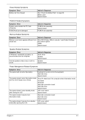
Keyboard (if contrast and brightness function key doesn't work LCD is too dark LCD brightness cannot be adjusted LCD contrast cannot be adjusted Unreadable LCD screen Missing pels in Sequence Enter BIOS Utility to -FRU Error Message LCD-Related Symptoms Symptom / Error LCD backlight doesn't work ). Action in Sequence Reconnect the inverter board Inverter board System board Power-Related Symptoms Symptom / Error Power shuts down during operation The system doesn't power-on. Battery pack Power adapter Hard drive & battery connection board System board Power source (battery pack and power ...
Keyboard (if contrast and brightness function key doesn't work LCD is too dark LCD brightness cannot be adjusted LCD contrast cannot be adjusted Unreadable LCD screen Missing pels in Sequence Enter BIOS Utility to -FRU Error Message LCD-Related Symptoms Symptom / Error LCD backlight doesn't work ). Action in Sequence Reconnect the inverter board Inverter board System board Power-Related Symptoms Symptom / Error Power shuts down during operation The system doesn't power-on. Battery pack Power adapter Hard drive & battery connection board System board Power source (battery pack and power ...
Service Guide
Page 121
.... Touchpad Keyboard Hard disk connection board Hard disk drive System board The system doesn't enter standby mode after opening the LCD. Press Fn+oand see if the computer enters hibernation mode. DIMM System board Speaker-Related Symptoms Symptom / Error In Windows, multimedia programs, no sound. Action in Sequence Audio driver Speaker System board Speaker System board Power Management-Related Symptoms Symptom / Error Action in Sequence See "Check the Battery Pack" on page 99. Power-Related Symptoms Symptom / Error Battery can't be charged...
.... Touchpad Keyboard Hard disk connection board Hard disk drive System board The system doesn't enter standby mode after opening the LCD. Press Fn+oand see if the computer enters hibernation mode. DIMM System board Speaker-Related Symptoms Symptom / Error In Windows, multimedia programs, no sound. Action in Sequence Audio driver Speaker System board Speaker System board Power Management-Related Symptoms Symptom / Error Action in Sequence See "Check the Battery Pack" on page 99. Power-Related Symptoms Symptom / Error Battery can't be charged...

Service Guide
Page 124
...are no error is detected, do not replace any error is detected, replace the FRU. When analyzing an intermittent problem, do with a hardware defect, such as: cosmic radiation, electrostatic discharge, or software errors. If any FRU. 3. If no more errors. 114 ...Chapter 4 Rerun the test to verify that have nothing to do the following: 1. Intermittent Problems Intermittent system hang problems can be considered only when a recurring problem exists. Run the advanced diagnostic test for the system board in loop mode...
...are no error is detected, do not replace any error is detected, replace the FRU. When analyzing an intermittent problem, do with a hardware defect, such as: cosmic radiation, electrostatic discharge, or software errors. If any FRU. 3. If no more errors. 114 ...Chapter 4 Rerun the test to verify that have nothing to do the following: 1. Intermittent Problems Intermittent system hang problems can be considered only when a recurring problem exists. Run the advanced diagnostic test for the system board in loop mode...


