
TravelMate 4060 Service Guide
Page 28
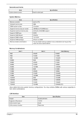
... 0MB 0MB 256MB 256MB 256MB 256MB 512MB 512MB 512MB 512MB 1024MB 1024MB 1024MB 1024MB Slot 1 256MB 512MB 1024MB 0MB 256MB 512MB 1024MB 0MB 256MB 512MB 1024MB 0MB 256MB 512MB 1024MB Slot 2 Total Memory 256MB 512MB 1024MB 256MB 512MB 768MB 1280MB 512MB 768MB 1024MB 1536MB 1024MB 1280MB 1536MB... 2048MB (2G) Above table lists some system memory configurations. LAN Interface Item Chipset Supports LAN protocol LAN connector...
... 0MB 0MB 256MB 256MB 256MB 256MB 512MB 512MB 512MB 512MB 1024MB 1024MB 1024MB 1024MB Slot 1 256MB 512MB 1024MB 0MB 256MB 512MB 1024MB 0MB 256MB 512MB 1024MB 0MB 256MB 512MB 1024MB Slot 2 Total Memory 256MB 512MB 1024MB 256MB 512MB 768MB 1280MB 512MB 768MB 1024MB 1536MB 1024MB 1280MB 1536MB... 2048MB (2G) Above table lists some system memory configurations. LAN Interface Item Chipset Supports LAN protocol LAN connector...
TravelMate 4060 Service Guide
Page 53
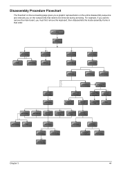
Start Battery HDD Module *2 HDD HDD Holder *2 Dimm Cover Memory *1 Modem Cover *2 Modem Board Hinge Caps *2 Middle Cover Keyboard *6 LCD Module *2 Launch Board Lower Case Assembly *2 FDD Module *3 *3 *11 *4 RTC Battery *3 ... Bracket *1 CPU Heatsink Plate *3 VGA Heatsink Plate Touchpad Button Pad *2 ODD Bracket ODD *4 Main Board Touchpad Touchpad Scroll Key *2 DC Board *4 PCMCIA Slot Touchpad Cable Upper Case *2 Speaker Set Chapter 3 44 Disassembly Procedure Flowchart The flowchart on the succeeding page gives you a graphic representation on the entire disassembly...
Start Battery HDD Module *2 HDD HDD Holder *2 Dimm Cover Memory *1 Modem Cover *2 Modem Board Hinge Caps *2 Middle Cover Keyboard *6 LCD Module *2 Launch Board Lower Case Assembly *2 FDD Module *3 *3 *11 *4 RTC Battery *3 ... Bracket *1 CPU Heatsink Plate *3 VGA Heatsink Plate Touchpad Button Pad *2 ODD Bracket ODD *4 Main Board Touchpad Touchpad Scroll Key *2 DC Board *4 PCMCIA Slot Touchpad Cable Upper Case *2 Speaker Set Chapter 3 44 Disassembly Procedure Flowchart The flowchart on the succeeding page gives you a graphic representation on the entire disassembly...
TravelMate 4060 Service Guide
Page 85
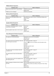
PCMCIA-Related Symptoms Symptom / Error System cannot detect the PC Card (PCMCIA) PCMCIA slot pin is from standby mode after closing the LCD See "S4 Sleeping State" on page 27. Action in Windows doesn't go higher than ... driver Speaker System board Speaker System board Action in Sequence Power Management-Related Symptoms Symptom / Error Action in Sequence PCMCIA slot assembly System board PCMCIA slot assembly Memory-Related Symptoms Symptom / Error Memory count (size) appears different from actual size. Remove battery pack and let it cool for 2 hours. LCD cover switch...
PCMCIA-Related Symptoms Symptom / Error System cannot detect the PC Card (PCMCIA) PCMCIA slot pin is from standby mode after closing the LCD See "S4 Sleeping State" on page 27. Action in Windows doesn't go higher than ... driver Speaker System board Speaker System board Action in Sequence Power Management-Related Symptoms Symptom / Error Action in Sequence PCMCIA slot assembly System board PCMCIA slot assembly Memory-Related Symptoms Symptom / Error Memory count (size) appears different from actual size. Remove battery pack and let it cool for 2 hours. LCD cover switch...

TravelMate 4060 User's Guide
Page 8
... 34 Connectivity options 34 Fax/data modem 34 Built-in network feature 35 Universal Serial Bus (USB) 35 IEEE 1394 port 36 PC Card slot 36 Installing memory 37 BIOS utility 38 Boot sequence 38 Enable disk-to-disk recovery 38 Password 39 Using software 39 Playing DVD movies 39 Power management...
... 34 Connectivity options 34 Fax/data modem 34 Built-in network feature 35 Universal Serial Bus (USB) 35 IEEE 1394 port 36 PC Card slot 36 Installing memory 37 BIOS utility 38 Boot sequence 38 Enable disk-to-disk recovery 38 Password 39 Using software 39 Playing DVD movies 39 Power management...

TravelMate 4060 User's Guide
Page 47
...steps to eject the card. English 37 Inserting a PC Card Insert the card into the slot and make the proper connections (e.g., network cable), if necessary. See your card manual for details. then press it again to install memory: 1 Turn off the computer, unplug the AC adapter (if connected) and remove the ... PC Card: 1 Exit the application using the card. 2 Left-click on the PC Card icon on the taskbar and stop the card operation. 3 Press the slot eject button to access its base. 2 Remove the screws from the memory cover; Then turn the computer over to pop out the eject button;
...steps to eject the card. English 37 Inserting a PC Card Insert the card into the slot and make the proper connections (e.g., network cable), if necessary. See your card manual for details. then press it again to install memory: 1 Turn off the computer, unplug the AC adapter (if connected) and remove the ... PC Card: 1 Exit the application using the card. 2 Left-click on the PC Card icon on the taskbar and stop the card operation. 3 Press the slot eject button to access its base. 2 Remove the screws from the memory cover; Then turn the computer over to pop out the eject button;
TravelMate 4060 User's Guide
Page 48
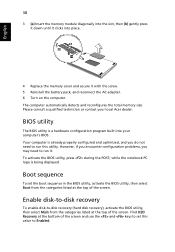
...D2D Recovery at the bottom of the screen and use the and keys to run it. The computer automatically detects and reconfigures the total memory size. Your computer is already properly configured and optimized, and you may need to set the boot sequence in the BIOS utility, activate ... disk-to-disk recovery To enable disk-to Enabled. Please consult a qualified technician or contact your computer's BIOS. English 38 3 (a) Insert the memory module diagonally into the slot, then (b) gently press it down until it clicks into your local Acer dealer. Boot sequence To set this utility.
...D2D Recovery at the bottom of the screen and use the and keys to run it. The computer automatically detects and reconfigures the total memory size. Your computer is already properly configured and optimized, and you may need to set the boot sequence in the BIOS utility, activate ... disk-to-disk recovery To enable disk-to Enabled. Please consult a qualified technician or contact your computer's BIOS. English 38 3 (a) Insert the memory module diagonally into the slot, then (b) gently press it down until it clicks into your local Acer dealer. Boot sequence To set this utility.


