
TravelMate 2350 Service Guide
Page 6
...Hot Keys 16 The Euro Symbol 17 Launch Keys 18 Touchpad 19 Hardware Specifications and Configurations 20 Chapter 2 System Utility 29 BIOS Setup Utility 29 BIOS Flash Utility 38 Chapter 3 Machine Disassembly and Replacement 39 General Information 40 Removing HDD Module, ODD and Memory Module 42 ...Removing the Keyboard/LCD Module 43 Chapter 4 Troubleshooting 50 System Check Procedures 50 Insyde MobilePro BIOS POST Beep Code and POST Messages 55 Index of Symptom-to-FRU Error Message 57 Undetermined Problems 60 Chapter 5 Jumper and Connector ...
...Hot Keys 16 The Euro Symbol 17 Launch Keys 18 Touchpad 19 Hardware Specifications and Configurations 20 Chapter 2 System Utility 29 BIOS Setup Utility 29 BIOS Flash Utility 38 Chapter 3 Machine Disassembly and Replacement 39 General Information 40 Removing HDD Module, ODD and Memory Module 42 ...Removing the Keyboard/LCD Module 43 Chapter 4 Troubleshooting 50 System Check Procedures 50 Insyde MobilePro BIOS POST Beep Code and POST Messages 55 Index of Symptom-to-FRU Error Message 57 Undetermined Problems 60 Chapter 5 Jumper and Connector ...

TravelMate 2350 Service Guide
Page 10
Mainboard Placement Top View Item JP1 JP5 JP6 JP7 JP8 JP9 JP10 JP11 JP12 JP13 JP15 JP16 JP17 Description CRT Connector RJ11/RJ45 Connector USB Connector x 2 CPU Fan Connector USB Connector Power Board Connector LVDS Connector MDC Connector CPU Socket MiniPCI Connector CardBus Connector HDD Connector ODD Connector Item JP18 JP19 JP20 JP22 JP23 JP24 U9 U12 PCN1 PJP9 SW1 SW3 Description Speaker Connector Touchpad Board Connector Microphone Jack Keyboard Connector Phone Jack LED Board Connector BIOS ROM North Bridge AC Jack Battery Connector LID Switch Kill Switch 4 Chapter 1
Mainboard Placement Top View Item JP1 JP5 JP6 JP7 JP8 JP9 JP10 JP11 JP12 JP13 JP15 JP16 JP17 Description CRT Connector RJ11/RJ45 Connector USB Connector x 2 CPU Fan Connector USB Connector Power Board Connector LVDS Connector MDC Connector CPU Socket MiniPCI Connector CardBus Connector HDD Connector ODD Connector Item JP18 JP19 JP20 JP22 JP23 JP24 U9 U12 PCN1 PJP9 SW1 SW3 Description Speaker Connector Touchpad Board Connector Microphone Jack Keyboard Connector Phone Jack LED Board Connector BIOS ROM North Bridge AC Jack Battery Connector LID Switch Kill Switch 4 Chapter 1

TravelMate 2350 Service Guide
Page 26
... FCBGA package Intel® Celeron® M Processor supports automatic selection of power supply voltage 1.05V BIOS Item BIOS vendor BIOS Version BIOS ROM type BIOS ROM size BIOS package Bupported protocols BIOS password control Second Level Cache Item Cache controller Cache size 1st level cache control 2nd level cache control ...package Memory module combinations Specification Insyde Insyde MobilePRO BIOS 4.0 Flash ROM 512KB 32 lead of PLCC ACPI 1.0b,PC Card 95, SM BIOS 2.3, EPP/IEEE 1284, ECP/IEEE 1284 1.7 & 1.9, PCI 2.2, PnP 1.0a, DMI 2.0, USB, VGA BIOS, CD-ROM bootable Set by setup manual ...
... FCBGA package Intel® Celeron® M Processor supports automatic selection of power supply voltage 1.05V BIOS Item BIOS vendor BIOS Version BIOS ROM type BIOS ROM size BIOS package Bupported protocols BIOS password control Second Level Cache Item Cache controller Cache size 1st level cache control 2nd level cache control ...package Memory module combinations Specification Insyde Insyde MobilePRO BIOS 4.0 Flash ROM 512KB 32 lead of PLCC ACPI 1.0b,PC Card 95, SM BIOS 2.3, EPP/IEEE 1284, ECP/IEEE 1284 1.7 & 1.9, PCI 2.2, PnP 1.0a, DMI 2.0, USB, VGA BIOS, CD-ROM bootable Set by setup manual ...

TravelMate 2350 Service Guide
Page 31
... Port Item PCMCIA controller Supports card type Number of slots Access location Supports ZV (Zoomed Video) port Supports 32 bit CardBus Specification Enable/Disable by BIOS setup ICH4-M Type II One type-II Left panel No ZV support Yes Specification System Board Major Chips Item System core logic Super I/O controller Audio...
... Port Item PCMCIA controller Supports card type Number of slots Access location Supports ZV (Zoomed Video) port Supports 32 bit CardBus Specification Enable/Disable by BIOS setup ICH4-M Type II One type-II Left panel No ZV support Yes Specification System Board Major Chips Item System core logic Super I/O controller Audio...

TravelMate 2350 Service Guide
Page 35
... Please also refer to save CMOS setting and exit Setup. Allows the user to Chapter 4 Troubleshooting when problem arises. To activate the BIOS Utility, press m during POST (when "Press to specify standard IBM PC AT system parameters Provides advanced settings of the system Provides security... settings of the system. Chapter 2 System Utilities BIOS Setup Utility The BIOS Setup Utility is enclosed in the Item Specific Help part of the screen. Main Advanced Security Boot Exit Item Description...
... Please also refer to save CMOS setting and exit Setup. Allows the user to Chapter 4 Troubleshooting when problem arises. To activate the BIOS Utility, press m during POST (when "Press to specify standard IBM PC AT system parameters Provides advanced settings of the system Provides security... settings of the system. Chapter 2 System Utilities BIOS Setup Utility The BIOS Setup Utility is enclosed in the Item Specific Help part of the screen. Main Advanced Security Boot Exit Item Description...

TravelMate 2350 Service Guide
Page 36
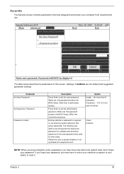
.... Insyde Software SCU Main Advanced Security Boot May 20, 2003 5:40:09 A Exit ----Devices System Product Name = TravelMate 2350 CPU = Intel® Pentium ® 4 Manufacture Name = Acer CPU speed = 1.4 GHz System BIOS Version =V1.00 VGA BIOS Version =3104 HDD Model Name= HITACHI_DK23EA-40-(PM) HDD Serial Number = 8D4648 ATAPI = UJDA740 DVD/CDROM-(SM) Serial...
.... Insyde Software SCU Main Advanced Security Boot May 20, 2003 5:40:09 A Exit ----Devices System Product Name = TravelMate 2350 CPU = Intel® Pentium ® 4 Manufacture Name = Acer CPU speed = 1.4 GHz System BIOS Version =V1.00 VGA BIOS Version =3104 HDD Model Name= HITACHI_DK23EA-40-(PM) HDD Serial Number = 8D4648 ATAPI = UJDA740 DVD/CDROM-(SM) Serial...
TravelMate 2350 Service Guide
Page 41
... suboptions are all requires the Supervisor password for changes and should be displayed The table below describes the parameters in this password protects the BIOS Setup Utility from unauthorized access. Don't forget your dealer to boot. No more than 8 characters Characters -- 0-9, A-Z (not case ...return your notebook computer to your password. Defines whether a password is required to reset it. Settings in this password protects the BIOS Setup Utility from unauthorized access. Allows the user to specify whether or not a password is required or not while the events...
... suboptions are all requires the Supervisor password for changes and should be displayed The table below describes the parameters in this password protects the BIOS Setup Utility from unauthorized access. Don't forget your dealer to boot. No more than 8 characters Characters -- 0-9, A-Z (not case ...return your notebook computer to your password. Defines whether a password is required to reset it. Settings in this password protects the BIOS Setup Utility from unauthorized access. Allows the user to specify whether or not a password is required or not while the events...
TravelMate 2350 Service Guide
Page 44
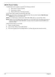
NOTE: Please use the Flash utility. Copy the Flash utilities to run the Flash utility. New features or options ! Restore a BIOS when it becomes corrupted. Fellow the steps below to the bootable diskette. 3. NOTE: If you do not have a crisis recovery ...the following conditions: ! Then boot the system from the bootable diskette. Use the Flash utility to finish BIOS flash, you use the Flash utilities. Prepare a bootable diskette. 2. BIOS Flash Utility The BIOS flash memory update is not completely loaded. The Flash utility has auto-execution function. 38 Chapter 2 ...
NOTE: Please use the Flash utility. Copy the Flash utilities to run the Flash utility. New features or options ! Restore a BIOS when it becomes corrupted. Fellow the steps below to the bootable diskette. 3. NOTE: If you do not have a crisis recovery ...the following conditions: ! Then boot the system from the bootable diskette. Use the Flash utility to finish BIOS flash, you use the Flash utilities. Prepare a bootable diskette. 2. BIOS Flash Utility The BIOS flash memory update is not completely loaded. The Flash utility has auto-execution function. 38 Chapter 2 ...

TravelMate 2350 Service Guide
Page 61
... long "FAULTY DMA PAGE REGISTERS" DMA page registers do not function properly. short, short, short; short, long, long "ROM CHECKSUM INCORRECT" BIOS ROM checksum failed. short, short, short; short, short, long; N/A "CMOS FAILURE - This index can also help you make changes in the...READ: xxxx" 55 Chapter 4 short, short, short; short, N/A short, long No RAM installed. RUN CMOS checksum error. Insyde MobilePro BIOS POST Beep Code and POST Messages The POST error message index lists the error message and their possible causes. Do not replace a non-...
... long "FAULTY DMA PAGE REGISTERS" DMA page registers do not function properly. short, short, short; short, long, long "ROM CHECKSUM INCORRECT" BIOS ROM checksum failed. short, short, short; short, short, long; N/A "CMOS FAILURE - This index can also help you make changes in the...READ: xxxx" 55 Chapter 4 short, short, short; short, N/A short, long No RAM installed. RUN CMOS checksum error. Insyde MobilePro BIOS POST Beep Code and POST Messages The POST error message index lists the error message and their possible causes. Do not replace a non-...

TravelMate 2350 Service Guide
Page 63
... adapter). Hold and press the power switch for more than 4 seconds. Main board See "Check the Power Adapter" on page 51". Action in Sequence Enter BIOS Utility to -FRU Error Message LCD-Related Symptoms Symptom / Error LCD backlight doesn't work ). Reconnect the LCD connectors. Battery pack Main board 57 Chapter 4 See...
... adapter). Hold and press the power switch for more than 4 seconds. Main board See "Check the Power Adapter" on page 51". Action in Sequence Enter BIOS Utility to -FRU Error Message LCD-Related Symptoms Symptom / Error LCD backlight doesn't work ). Reconnect the LCD connectors. Battery pack Main board 57 Chapter 4 See...

TravelMate 2350 Service Guide
Page 65
...the telephone cable is firmly connected into the telephone wall socket and the modem port of BIOS Setup Utility is secured to execute "Load Setup defaults", then reboot system. Then check if RAM CPU BIOS are well-connected. Main board Ensure the "Parallel Port" in Sequence Reconnect the keyboard ... "System Devices" of the computer. modem combo board Main board NOTE: If you cannot find a symptom or an error in Sequence Enter BIOS Setup Utility to the main board Touch pad FPC Audio/Touch pad board Main board Modem-Related Symptoms Symptom / Error Action in Sequence Internal modem...
...the telephone cable is firmly connected into the telephone wall socket and the modem port of BIOS Setup Utility is secured to execute "Load Setup defaults", then reboot system. Then check if RAM CPU BIOS are well-connected. Main board Ensure the "Parallel Port" in Sequence Reconnect the keyboard ... "System Devices" of the computer. modem combo board Main board NOTE: If you cannot find a symptom or an error in Sequence Enter BIOS Setup Utility to the main board Touch pad FPC Audio/Touch pad board Main board Modem-Related Symptoms Symptom / Error Action in Sequence Internal modem...

TravelMate 2350 Service Guide
Page 67
CPU Socket MINIPCI CONN. CARDBUS CONN. Chapter 5 Item JP18 JP19 JP20 JP22 JP23 JP24 U9 U12 PCN1 PJP9 SW1 SW3 Description SPK CONN. TP/B CONN. BIOS ROM NB AC JACK BATT. LVDS CONN. CONN. POWER/B CONN. LID SWITCH KILL SWITCH 61 HDD CONN. MIC JACK K/B CONN. PHONE JACK LED/B CONN. Jumper and Connector Locations Top View Chapter 5 Item JP1 JP5 JP6 JP7 JP8 JP9 JP10 JP11 JP12 JP13 JP15 JP16 Description CRT CONN RJ11/RJ45 CONN. USB CONN X2 CPU FAN CONN USB CONN. MBC CONN.
CPU Socket MINIPCI CONN. CARDBUS CONN. Chapter 5 Item JP18 JP19 JP20 JP22 JP23 JP24 U9 U12 PCN1 PJP9 SW1 SW3 Description SPK CONN. TP/B CONN. BIOS ROM NB AC JACK BATT. LVDS CONN. CONN. POWER/B CONN. LID SWITCH KILL SWITCH 61 HDD CONN. MIC JACK K/B CONN. PHONE JACK LED/B CONN. Jumper and Connector Locations Top View Chapter 5 Item JP1 JP5 JP6 JP7 JP8 JP9 JP10 JP11 JP12 JP13 JP15 JP16 Description CRT CONN RJ11/RJ45 CONN. USB CONN X2 CPU FAN CONN USB CONN. MBC CONN.

TravelMate 2350 Service Guide
Page 89
... section describes online technical support services available to help you repair your Acer Systems. If you can be obtained directly from Acer CSD Taiwan. Also contained on Acer's International Traveler's Warranty (ITW) ! Acer's Website offers you convenient and valuable support resources whenever you have included... the problem-free downloading of telephone, fax and email contacts for all your technical queries. Acer Branch Offices and Regional Business Units may access our website. Bios updates ! However some information sources will require a user i.d. Software utilities !
... section describes online technical support services available to help you repair your Acer Systems. If you can be obtained directly from Acer CSD Taiwan. Also contained on Acer's International Traveler's Warranty (ITW) ! Acer's Website offers you convenient and valuable support resources whenever you have included... the problem-free downloading of telephone, fax and email contacts for all your technical queries. Acer Branch Offices and Regional Business Units may access our website. Bios updates ! However some information sources will require a user i.d. Software utilities !


