
TravelMate 2100/2600 Service Guide
Page 9
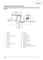
Board Layout Top View 1 Line-in Port 2 Line-out Port 3 RJ45+RJ11 4 LCD Inverter Cable Connector 5 USB Port 6 USB Port 7 USB Port 8 USB Port 9 VGA Port 10 S-Video Port 11 LCD Coaxial Cable Connector 12 Parallel Port 13 DC-in Port 14 LCD Lid Switch 15 CPU Socket 16 North Bridge 17 Fan Connector 18 Second Fan Connector 19 Touchpad Cable Connector 20 HDD Connector 21 Keyboard Connector 22 Speaker Cable Connector 23 Optical Drive Connector 24 South Bridge 25 RTC Battery Connector 26 Launch Board Cable Connector 27 SW5 (Please see Chapter 5 for its settings) 28 PCMCIA Slot 4 Chapter 1
Board Layout Top View 1 Line-in Port 2 Line-out Port 3 RJ45+RJ11 4 LCD Inverter Cable Connector 5 USB Port 6 USB Port 7 USB Port 8 USB Port 9 VGA Port 10 S-Video Port 11 LCD Coaxial Cable Connector 12 Parallel Port 13 DC-in Port 14 LCD Lid Switch 15 CPU Socket 16 North Bridge 17 Fan Connector 18 Second Fan Connector 19 Touchpad Cable Connector 20 HDD Connector 21 Keyboard Connector 22 Speaker Cable Connector 23 Optical Drive Connector 24 South Bridge 25 RTC Battery Connector 26 Launch Board Cable Connector 27 SW5 (Please see Chapter 5 for its settings) 28 PCMCIA Slot 4 Chapter 1
TravelMate 2100/2600 Service Guide
Page 24
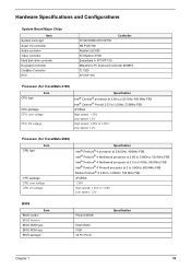
... Radeon 9700 Embedded in ATI IXP 150 Mitsubish LPC keyboard controller M38857 TI 1520 ATI IXP 150 Processor (for TravelMate 2100) CPU type Item CPU package CPU core voltage CPU I/O voltage Specification Intel® Cerelon® processor at 2.40 to 2.80 GHz; 400 MHz FSB Intel&#...533MHz FSB uFCBGA High speed: 1.35V Low speed: 1.2V High speed: 1.35V or 1.55V Low speed: 1.2V Processor (for TravelMate 2600) CPU type Item CPU package CPU core voltage CPU I/O voltage Specification Intel® Pentium® 4 processor at 2.60GHz, 400Mhz FSB Intel® Pentium® 4 Northwood processor ...
... Radeon 9700 Embedded in ATI IXP 150 Mitsubish LPC keyboard controller M38857 TI 1520 ATI IXP 150 Processor (for TravelMate 2100) CPU type Item CPU package CPU core voltage CPU I/O voltage Specification Intel® Cerelon® processor at 2.40 to 2.80 GHz; 400 MHz FSB Intel&#...533MHz FSB uFCBGA High speed: 1.35V Low speed: 1.2V High speed: 1.35V or 1.55V Low speed: 1.2V Processor (for TravelMate 2600) CPU type Item CPU package CPU core voltage CPU I/O voltage Specification Intel® Pentium® 4 processor at 2.60GHz, 400Mhz FSB Intel® Pentium® 4 Northwood processor ...
TravelMate 2100/2600 Service Guide
Page 25
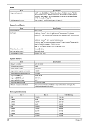
...256MB 256MB 384MB 384MB 512MB 512MB Chapter 1 Specification Built-in CPU 128KB for Cerelon® CPU; 512KB for Intel® Northwood CPU, Mobile Pentium® 4 CPU and Cerelon® Prescott CPU; 1MB for Intel® Prescott CPU 128KB for Cerelon® CPU used in TM2000 series 512KB for Intel® Northwood, ...Mobile Pentium® 4 and Cerelon® Prescott CPU used in TM2500 series and TM2000 series 1MB for Intel® Prescott CPU used in TM2500 series Always Enabled Always Enabled Fixed-in write back System Memory Item Memory controller ...
...256MB 256MB 384MB 384MB 512MB 512MB Chapter 1 Specification Built-in CPU 128KB for Cerelon® CPU; 512KB for Intel® Northwood CPU, Mobile Pentium® 4 CPU and Cerelon® Prescott CPU; 1MB for Intel® Prescott CPU 128KB for Cerelon® CPU used in TM2000 series 512KB for Intel® Northwood, ...Mobile Pentium® 4 and Cerelon® Prescott CPU used in TM2500 series and TM2000 series 1MB for Intel® Prescott CPU used in TM2500 series Always Enabled Always Enabled Fixed-in write back System Memory Item Memory controller ...

TravelMate 2100/2600 Service Guide
Page 42
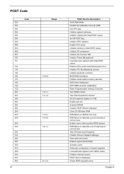
... address of the parallel port. 378/278 Sets the interrupt request of the parallel port. The table below 3.06G or the CPU does not support Hyper-Threading Technoloty. Enabled/Disabled Enables, disables or auto detects the infrared port. Enabled/Disabled/Auto Sets the ...disables or auto detects the parallel port. directional Sets the I /O address Interrupt Description Options The function is supported only when the CPU installed is below describes the parameters in boldface are the default and suggested parameter settings. . Advanced The Advanced menu screen contains ...
... address of the parallel port. 378/278 Sets the interrupt request of the parallel port. The table below 3.06G or the CPU does not support Hyper-Threading Technoloty. Enabled/Disabled Enables, disables or auto detects the infrared port. Enabled/Disabled/Auto Sets the ...disables or auto detects the parallel port. directional Sets the I /O address Interrupt Description Options The function is supported only when the CPU installed is below describes the parameters in boldface are the default and suggested parameter settings. . Advanced The Advanced menu screen contains ...

TravelMate 2100/2600 Service Guide
Page 53
... Second Fan J*3 Bracket Lower Case Assembly J*2 FDD Module J*5 F*10 D*4 Upper Case Assembly D*4 Wireless LAN Antenna Touchpad Cover J*3 Second Fan *4 Thermal Module CPU ODD Module J*4 HDD Bracket F*1 ODD Support Bracket *1 CPU Heatsink Plate J*7 VGA Thermal Plate Touchpad Button Pad D*2 ODD Bracket ODD *4 Main Board Touchpad Touchpad Scroll Key D*2 DC Board D*4 PCMCIA Slot Touchpad...
... Second Fan J*3 Bracket Lower Case Assembly J*2 FDD Module J*5 F*10 D*4 Upper Case Assembly D*4 Wireless LAN Antenna Touchpad Cover J*3 Second Fan *4 Thermal Module CPU ODD Module J*4 HDD Bracket F*1 ODD Support Bracket *1 CPU Heatsink Plate J*7 VGA Thermal Plate Touchpad Button Pad D*2 ODD Bracket ODD *4 Main Board Touchpad Touchpad Scroll Key D*2 DC Board D*4 PCMCIA Slot Touchpad...

TravelMate 2100/2600 Service Guide
Page 67
Then remove the CPU. See "Removing the Battery" on page 61. 5. See "Removing the Fan" on page 50. 2. See "Removing the Fan" on page 50. 2. See "Removing the Battery" ... "Removing the Middle Cover" on page 54. 3. See "Removing the Keyboard" on page 61. 5. See "Removing the RTC Battery" on page 61. 4. Lift up the CPU socket lever. Remember to press down the lever as the video shows after you remove the...
Then remove the CPU. See "Removing the Battery" on page 61. 5. See "Removing the Fan" on page 50. 2. See "Removing the Fan" on page 50. 2. See "Removing the Battery" ... "Removing the Middle Cover" on page 54. 3. See "Removing the Keyboard" on page 61. 5. See "Removing the RTC Battery" on page 61. 4. Lift up the CPU socket lever. Remember to press down the lever as the video shows after you remove the...

TravelMate 2100/2600 Service Guide
Page 68
... the touchpad cable. 3. See "Removing the Middle Cover" on page 61. 2. Lift up the CPU lever, then place the CPU back to the socket. Please remember to press the CPU lever after you put the CPU back to the CPU socket. Removing the Upper Case Assemly 1. See "Removing the Keyboard" on page 54. 3. See "Removing...
... the touchpad cable. 3. See "Removing the Middle Cover" on page 61. 2. Lift up the CPU lever, then place the CPU back to the socket. Please remember to press the CPU lever after you put the CPU back to the CPU socket. Removing the Upper Case Assemly 1. See "Removing the Keyboard" on page 54. 3. See "Removing...

TravelMate 2100/2600 Service Guide
Page 70
See "Removing the LCD Module" on page 61. 5. See "Removing the Fan" on page 55. 4. Removing the CPU Heatsink Plate 1. See "Removing the Touchpad Board" on page 61. 4. Removing the VGA Thermal Plate 1. See "Removing the Keyboard" on page 64. 7. See "Removing the ...Thermal Module" on page 54. 3. Remove the seven screws holding the VGA thermal plate then remove it . 65 Chapter 3 Remove the screw that fastens the CPU heatsink plate then remove it . See "Removing the Middle Cover" on page 62. 6. See "Removing the Middle Cover" on page 50. 2. See "Removing the Battery...
See "Removing the LCD Module" on page 61. 5. See "Removing the Fan" on page 55. 4. Removing the CPU Heatsink Plate 1. See "Removing the Touchpad Board" on page 61. 4. Removing the VGA Thermal Plate 1. See "Removing the Keyboard" on page 64. 7. See "Removing the ...Thermal Module" on page 54. 3. Remove the seven screws holding the VGA thermal plate then remove it . 65 Chapter 3 Remove the screw that fastens the CPU heatsink plate then remove it . See "Removing the Middle Cover" on page 62. 6. See "Removing the Middle Cover" on page 50. 2. See "Removing the Battery...

TravelMate 2100/2600 Service Guide
Page 72
..., then remove the HDD bracket. See "Removing the VGA Thermal Plate" on page 67. 12. See "Removing the Battery" on page 65. 9. See "Removing the CPU Heatsink Plate" on page 50. 2. Tear off the tape that fastens the speaker set cable. 67 Chapter 3 See "Removing the Keyboard" on page 66. 10...
..., then remove the HDD bracket. See "Removing the VGA Thermal Plate" on page 67. 12. See "Removing the Battery" on page 65. 9. See "Removing the CPU Heatsink Plate" on page 50. 2. Tear off the tape that fastens the speaker set cable. 67 Chapter 3 See "Removing the Keyboard" on page 66. 10...

TravelMate 2100/2600 Service Guide
Page 73
... page 50. 2. See "Removing the Keyboard" on page 61. 6. See "Removing the Fan" on page 61. 4. Removing the I/O Port Bracket 1. Chapter 3 68 See "Removing the CPU Heatsink Plate" on page 63. 5. Remove the two screws holding the main board as the picture shows. See "Removing the Upper Case Assemly" on page...
... page 50. 2. See "Removing the Keyboard" on page 61. 6. See "Removing the Fan" on page 61. 4. Removing the I/O Port Bracket 1. Chapter 3 68 See "Removing the CPU Heatsink Plate" on page 63. 5. Remove the two screws holding the main board as the picture shows. See "Removing the Upper Case Assemly" on page...

TravelMate 2100/2600 Service Guide
Page 74
... on page 54. 3. See "Removing the Middle Cover" on page 67. 13. See "Removing the Upper Case Assemly" on page 65. 9. See "Removing the CPU Heatsink Plate" on page 63. 5. See "Removing the Main Board" on page 66. 11. See "Removing the ODD Module(2)" on page 67. 13. See "Removing... the Fan" on page 66. 11. See "Removing the ODD Module(2)" on page 61. 6. See "Removing the Fan" on page 65. 9. See "Removing the CPU Heatsink Plate" on page 61. 6. See "Removing the Keyboard" on page 65. 8. See "Removing the VGA Thermal Plate" on page 61. 4. Remove the four hex...
... on page 54. 3. See "Removing the Middle Cover" on page 67. 13. See "Removing the Upper Case Assemly" on page 65. 9. See "Removing the CPU Heatsink Plate" on page 63. 5. See "Removing the Main Board" on page 66. 11. See "Removing the ODD Module(2)" on page 67. 13. See "Removing... the Fan" on page 66. 11. See "Removing the ODD Module(2)" on page 61. 6. See "Removing the Fan" on page 65. 9. See "Removing the CPU Heatsink Plate" on page 61. 6. See "Removing the Keyboard" on page 65. 8. See "Removing the VGA Thermal Plate" on page 61. 4. Remove the four hex...

TravelMate 2100/2600 Service Guide
Page 75
... tape fastening the speaker set . See "Removing the Middle Cover" on page 67. 13. See "Removing the Thermal Module" on page 65. 9. See "Removing the CPU Heatsink Plate" on page 62. 7. Then remove the four screws that secure the speaker set cable. Remove the speaker set from the lower case. See...
... tape fastening the speaker set . See "Removing the Middle Cover" on page 67. 13. See "Removing the Thermal Module" on page 65. 9. See "Removing the CPU Heatsink Plate" on page 62. 7. Then remove the four screws that secure the speaker set cable. Remove the speaker set from the lower case. See...
TravelMate 2100/2600 Service Guide
Page 83
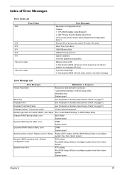
... "Keyboard or Auxiliary Input Device Check" on page 73. Unlock key switch Unlock external keyboard Monitor type does not match CMOS - System board Chapter 4 78 CPU BIOS Update Code Mismatch 2. Hard disk drive System board Stuck Key see "Keyboard or Auxiliary Input Device Check" on page 73.
... "Keyboard or Auxiliary Input Device Check" on page 73. Unlock key switch Unlock external keyboard Monitor type does not match CMOS - System board Chapter 4 78 CPU BIOS Update Code Mismatch 2. Hard disk drive System board Stuck Key see "Keyboard or Auxiliary Input Device Check" on page 73.

TravelMate 2100/2600 Service Guide
Page 84
... properly identified. Incorrect Drive A type - RTC battery System board Allocation Error for device Run "Load Default Settings" in BIOS Setup Utility. Cache disabled System board CPU ID: System board DMA Test Failed DIMM System board Software NMI Failed DIMM System board Fail-Safe Timer NMI Failed DIMM System board Device Address...
... properly identified. Incorrect Drive A type - RTC battery System board Allocation Error for device Run "Load Default Settings" in BIOS Setup Utility. Cache disabled System board CPU ID: System board DMA Test Failed DIMM System board Software NMI Failed DIMM System board Fail-Safe Timer NMI Failed DIMM System board Device Address...
TravelMate 2100/2600 Service Guide
Page 86
...initial POST values Initialize I/O component Initialize the local bus IDE Initialize Power Management Load alternate registers with initial POST values Restore CPU control word during warm boot Initialize PCI Bus Mastering devices Initialize keyboard controller BIOS ROM checksum Initialize cache before memory autosize 8254...of memory bus Enable cache before system BIOS shadow RAM failure on data bits xxxx of high byte of memory bus Test CPU bus-clock frequency Initialize Phoenix Dispatch Manager Warm start shut down Shadow system BIOS ROM Autosize cache Advanced configuration of chipset ...
...initial POST values Initialize I/O component Initialize the local bus IDE Initialize Power Management Load alternate registers with initial POST values Restore CPU control word during warm boot Initialize PCI Bus Mastering devices Initialize keyboard controller BIOS ROM checksum Initialize cache before memory autosize 8254...of memory bus Enable cache before system BIOS shadow RAM failure on data bits xxxx of high byte of memory bus Test CPU bus-clock frequency Initialize Phoenix Dispatch Manager Warm start shut down Shadow system BIOS ROM Autosize cache Advanced configuration of chipset ...
TravelMate 2100/2600 Service Guide
Page 87
... bus and devices Initialize all video adapters in system QuietBoot start (optional) Shadow video BIOS ROM Display BIOS copyright notice Display CPU type and speed Initialize EISA board Test keyboard Set key click if enabled Test for unexpected interrupts Initialize POST display service Display ...Test extended memory Test extended memory address lines Jump to User Patch1 Configure advanced cache registers Initialize Multi Processor APIC Enable external and CPU caches Setup System Management Mode (SMM) area Display external L2 cache size Load custom defaults (optional) Display shadow-area message ...
... bus and devices Initialize all video adapters in system QuietBoot start (optional) Shadow video BIOS ROM Display BIOS copyright notice Display CPU type and speed Initialize EISA board Test keyboard Set key click if enabled Test for unexpected interrupts Initialize POST display service Display ...Test extended memory Test extended memory address lines Jump to User Patch1 Configure advanced cache registers Initialize Multi Processor APIC Enable external and CPU caches Setup System Management Mode (SMM) area Display external L2 cache size Load custom defaults (optional) Display shadow-area message ...
TravelMate 2100/2600 Service Guide
Page 89
... EEh EFh F0h F1h F2h F3h F4h F5h F6h F7h Beeps 1 For Boot Block in Flash ROM Initialize the chipset Initialize the bridge Initialize the CPU Initialize the system timer Initialize system I/O Check force recovery boot Checksum BIOS ROM Go to BIOS Set Huge Segment Initialize Multi Processor Initialize OEM special...
... EEh EFh F0h F1h F2h F3h F4h F5h F6h F7h Beeps 1 For Boot Block in Flash ROM Initialize the chipset Initialize the bridge Initialize the CPU Initialize the system timer Initialize system I/O Check force recovery boot Checksum BIOS ROM Go to BIOS Set Huge Segment Initialize Multi Processor Initialize OEM special...
TravelMate 2100/2600 Service Guide
Page 103
... Port 8 USB Port 9 VGA Port 10 S-Video Port 11 LCD Coaxial Cable Connector 12 Parallel Port 13 DC-in Port 14 LCD Lid Switch 15 CPU Socket 16 North Bridge 17 Fan Connector 18 Second Fan Connector 19 Touchpad Cable Connector 20 HDD Connector 21 Keyboard Connector 22 Speaker Cable Connector...
... Port 8 USB Port 9 VGA Port 10 S-Video Port 11 LCD Coaxial Cable Connector 12 Parallel Port 13 DC-in Port 14 LCD Lid Switch 15 CPU Socket 16 North Bridge 17 Fan Connector 18 Second Fan Connector 19 Touchpad Cable Connector 20 HDD Connector 21 Keyboard Connector 22 Speaker Cable Connector...

TravelMate 2100/2600 Service Guide
Page 110
... Communication Module WIRELESS ANTENNA RIGHT (BLACK) 50.A20V1.001 WIRELESS ANTENNA LEFT (GRAY) 50.A20V1.002 CPU HDD/ Hard Disk Drive 105 CPU 2.6GMHZ 400FSB INTEL CPU 2.8GMHZ 400FSB INTEL CPU 2.4GMHZ 400FSB INTEL CPU 2.5GMHZ 400FSB INTEL CPU 2.7GMHZ 400FSB INTEL KC.DCD01.26A KC.DCD01.28A KC.DCD01.24A KC.DCD01.25A KC.DCD01... HDD 40G FUJITSU MHT2040AT 0022 A3 KH.04006.004 HDD 40G 4200PRM SEAGATE ST94019A KH.04001.010 HDD 60G HITACHI C25N060ATMR04 KH.06007.006 Chapter 6 TravelMate 2100 FRU List Picture No.
... Communication Module WIRELESS ANTENNA RIGHT (BLACK) 50.A20V1.001 WIRELESS ANTENNA LEFT (GRAY) 50.A20V1.002 CPU HDD/ Hard Disk Drive 105 CPU 2.6GMHZ 400FSB INTEL CPU 2.8GMHZ 400FSB INTEL CPU 2.4GMHZ 400FSB INTEL CPU 2.5GMHZ 400FSB INTEL CPU 2.7GMHZ 400FSB INTEL KC.DCD01.26A KC.DCD01.28A KC.DCD01.24A KC.DCD01.25A KC.DCD01... HDD 40G FUJITSU MHT2040AT 0022 A3 KH.04006.004 HDD 40G 4200PRM SEAGATE ST94019A KH.04001.010 HDD 60G HITACHI C25N060ATMR04 KH.06007.006 Chapter 6 TravelMate 2100 FRU List Picture No.

TravelMate 2100/2600 Service Guide
Page 111
TravelMate 2100 FRU List Picture No. 16 Partname And Description Part Number HDD 60G HITACHI DK23FA-60 A0A0 KH.06007.005 HDD 60G TOSHIBA MK6021GAS KH.36004.... HITACHI IC25N080ATMR04 KH.08007.002 HDD 80G TOSHIBA MK8025GAS KA023A KH.08004.001 HDD HOLDER 33.E02V1.001 Heatsink Keyboard Chapter 6 VGA THERMAL PLATE CPU THERMAL PLATE CPU FANSINK 33.A20V1.003 34.A30V1.001 34.A20V1.102 2 KEYBOARD DARFON NSK-ACY1D KB.A2007.001 USI KEYBOARD DARFON NSK-ACY0U UK KEYBOARD...
TravelMate 2100 FRU List Picture No. 16 Partname And Description Part Number HDD 60G HITACHI DK23FA-60 A0A0 KH.06007.005 HDD 60G TOSHIBA MK6021GAS KH.36004.... HITACHI IC25N080ATMR04 KH.08007.002 HDD 80G TOSHIBA MK8025GAS KA023A KH.08004.001 HDD HOLDER 33.E02V1.001 Heatsink Keyboard Chapter 6 VGA THERMAL PLATE CPU THERMAL PLATE CPU FANSINK 33.A20V1.003 34.A30V1.001 34.A20V1.102 2 KEYBOARD DARFON NSK-ACY1D KB.A2007.001 USI KEYBOARD DARFON NSK-ACY0U UK KEYBOARD...

