
TravelMate 2000/2500 Service Guide
Page 8
... CPU Heatsink Plate 67 Removing the Second Fan Bracket 68 Removing the ODD Module(1 68 Removing the ODD Module(2 68 Removing the HDD Bracket 69 Removing the Main Board 69 Removing the DC Board 70 Removing the I/O Port Bracket 70 Removing the PCMCIA Slot 71...Disk Recovery 91 Chapter 5 Jumper and Connector Locations 96 Top View 96 Bottom View 97 Chapter 6 FRU (Field Replaceable Unit) List 98 TravelMate 2000/2500 Exploded Diagram 99 Appendix A Model Definition and Configuration 110 Model Name Definition 110 Appendix B Test Compatible Components 112 Microsoft Windows XP ...
... CPU Heatsink Plate 67 Removing the Second Fan Bracket 68 Removing the ODD Module(1 68 Removing the ODD Module(2 68 Removing the HDD Bracket 69 Removing the Main Board 69 Removing the DC Board 70 Removing the I/O Port Bracket 70 Removing the PCMCIA Slot 71...Disk Recovery 91 Chapter 5 Jumper and Connector Locations 96 Top View 96 Bottom View 97 Chapter 6 FRU (Field Replaceable Unit) List 98 TravelMate 2000/2500 Exploded Diagram 99 Appendix A Model Definition and Configuration 110 Model Name Definition 110 Appendix B Test Compatible Components 112 Microsoft Windows XP ...

TravelMate 2000/2500 Service Guide
Page 12
Board Layout Top View 1 Line-in Port 2 Line-out Port 3 RJ45+RJ11 4 LCD Inverter Cable Connector 5 USB Port 6 USB Port 7 USB Port 8 USB Port 9 VGA Port 10 S-Video Port 11 LCD Coaxial Cable Connector 12 Parallel Port 13 DC-in Port 14 LCD Lid Switch 15 CPU Socket 16 North Bridge 17 Fan Connector 18 Second Fan Connector 19 Touchpad Cable Connector 20 HDD Connector 21 Keyboard Connector 22 Speaker Cable Connector 23 Optical Drive Connector 24 South Bridge 25 RTC Battery Connector 26 Launch Board Cable Connector 27 SW5 (Please see Chapter 5 for its settings) 28 PCMCIA Slot 4 Chapter 1
Board Layout Top View 1 Line-in Port 2 Line-out Port 3 RJ45+RJ11 4 LCD Inverter Cable Connector 5 USB Port 6 USB Port 7 USB Port 8 USB Port 9 VGA Port 10 S-Video Port 11 LCD Coaxial Cable Connector 12 Parallel Port 13 DC-in Port 14 LCD Lid Switch 15 CPU Socket 16 North Bridge 17 Fan Connector 18 Second Fan Connector 19 Touchpad Cable Connector 20 HDD Connector 21 Keyboard Connector 22 Speaker Cable Connector 23 Optical Drive Connector 24 South Bridge 25 RTC Battery Connector 26 Launch Board Cable Connector 27 SW5 (Please see Chapter 5 for its settings) 28 PCMCIA Slot 4 Chapter 1

TravelMate 2000/2500 Service Guide
Page 40
...-in touchpad, and an external PS/2 pointing device are idle for a specified period. Power Management Power Saving Mode Hibernation Mode Enter Hibernation Mode (suspend to HDD) when 1.Hibernation hot-key is pressed and system is ready to enter Hibernation mode 2.System Hibernation timer expires and system is in standby mode. (spindle...
...-in touchpad, and an external PS/2 pointing device are idle for a specified period. Power Management Power Saving Mode Hibernation Mode Enter Hibernation Mode (suspend to HDD) when 1.Hibernation hot-key is pressed and system is ready to enter Hibernation mode 2.System Hibernation timer expires and system is in standby mode. (spindle...

TravelMate 2000/2500 Service Guide
Page 44
...2000 and TravelMate 2000 series have floppy disk drive; This field shows the serial number of this unit. This field displays the serial number of devices installed on primary IDE master. The hard disk drive or optical drive model name is presenting. This field displays the serial number of HDD...=32bytes Chapter 2 36 Parameter Floppy Disk Drive HDD Model Name HDD Serial Number ATAPI Model Name ATAPI Serial Number Serial Number UUID Number Description Shows floppy drive type informaiton. Note: Aspre 1620, Extensa 2700, TravelMate 2500 and Extnesa 2500 series products do not ...
...2000 and TravelMate 2000 series have floppy disk drive; This field shows the serial number of this unit. This field displays the serial number of devices installed on primary IDE master. The hard disk drive or optical drive model name is presenting. This field displays the serial number of HDD...=32bytes Chapter 2 36 Parameter Floppy Disk Drive HDD Model Name HDD Serial Number ATAPI Model Name ATAPI Serial Number Serial Number UUID Number Description Shows floppy drive type informaiton. Note: Aspre 1620, Extensa 2700, TravelMate 2500 and Extnesa 2500 series products do not ...
TravelMate 2000/2500 Service Guide
Page 50
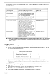
... is set . The Set Supervisor Password box appears: 2. When you have to return your notebook computer to enabled. Password can unlock the HDD. Setting a Password Follow these steps as you are set to your password because the characters do not appear on...Shows the setting of the user password. Press e. Settings in boldface are all requires the Supervisor password for changes and should be written on HDD only when Supervisor password or user password is set . The following sub-options are the default and suggested parameter settings. After setting the ...
... is set . The Set Supervisor Password box appears: 2. When you have to return your notebook computer to enabled. Password can unlock the HDD. Setting a Password Follow these steps as you are set to your password because the characters do not appear on...Shows the setting of the user password. Press e. Settings in boldface are all requires the Supervisor password for changes and should be written on HDD only when Supervisor password or user password is set . The following sub-options are the default and suggested parameter settings. After setting the ...

TravelMate 2000/2500 Service Guide
Page 58
... first remove the keyboard, then disassemble the inside assembly frame in that need to be removed during servicing. Start Battery HDD Module G*2 HDD HDD Holder *2 DIMM Cover Memory *2 Modem Cover Hinge Caps Wireless LAN Board D*2 Modem Board J*2 Middle Cover RTC Battery ... J*2 FDD Module J*5 F*10 D*4 Upper Case Assembly D*4 Wireless LAN Antenna Touchpad Cover J*3 Second Fan *4 Thermal Module CPU ODD Module J*4 HDD Bracket F*1 ODD Support Bracket *1 CPU Heatsink Plate J*7 VGA Thermal Plate Touchpad Button Pad D*2 ODD Bracket ODD *4 Main Board Touchpad Touchpad Scroll...
... first remove the keyboard, then disassemble the inside assembly frame in that need to be removed during servicing. Start Battery HDD Module G*2 HDD HDD Holder *2 DIMM Cover Memory *2 Modem Cover Hinge Caps Wireless LAN Board D*2 Modem Board J*2 Middle Cover RTC Battery ... J*2 FDD Module J*5 F*10 D*4 Upper Case Assembly D*4 Wireless LAN Antenna Touchpad Cover J*3 Second Fan *4 Thermal Module CPU ODD Module J*4 HDD Bracket F*1 ODD Support Bracket *1 CPU Heatsink Plate J*7 VGA Thermal Plate Touchpad Button Pad D*2 ODD Bracket ODD *4 Main Board Touchpad Touchpad Scroll...

TravelMate 2000/2500 Service Guide
Page 63
Then take the hard disk drive out of the main unit. Removing the Hard Disk Drive Module 1. To remove the hard disk drive, pull the hard disk dirve carefully. 3. Disassembling the Hard Disk Drive Module 1. Remove the two screws that fasten the HDD holder. 4. Detach the hard disk drive from the HDD holder. 55 Chapter 3 See "Removing the Hard Disk Drive Module" on page 52. 2. See "Removing the Battery" on page 55. 3. See "Removing the Battery" on page 52. 2.
Then take the hard disk drive out of the main unit. Removing the Hard Disk Drive Module 1. To remove the hard disk drive, pull the hard disk dirve carefully. 3. Disassembling the Hard Disk Drive Module 1. Remove the two screws that fasten the HDD holder. 4. Detach the hard disk drive from the HDD holder. 55 Chapter 3 See "Removing the Hard Disk Drive Module" on page 52. 2. See "Removing the Battery" on page 55. 3. See "Removing the Battery" on page 52. 2.

TravelMate 2000/2500 Service Guide
Page 77
... page 65. 5. See "Removing the Upper Case Assemly" on page 56. 3. See "Removing the HDD Bracket" on page 63. 4. Remove the four screws holding the HDD bracket, then remove the HDD bracket. See "Removing the Keyboard" on page 69. 12. Removing the Main Board 1. Disconnect the ...launch board cable. Removing the HDD Bracket 1. See "Removing the Battery" on page 56. 3. See "Removing the Middle...
... page 65. 5. See "Removing the Upper Case Assemly" on page 56. 3. See "Removing the HDD Bracket" on page 63. 4. Remove the four screws holding the HDD bracket, then remove the HDD bracket. See "Removing the Keyboard" on page 69. 12. Removing the Main Board 1. Disconnect the ...launch board cable. Removing the HDD Bracket 1. See "Removing the Battery" on page 56. 3. See "Removing the Middle...

TravelMate 2000/2500 Service Guide
Page 78
... page 69. 13. Then detach the DC board from the lower case carefully. See "Removing the Middle Cover" on page 69. 12. See "Removing the HDD Bracket" on page 56. See "Removing the Upper Case Assemly" on page 52. 2. Then detach the main board from the lower case. See "Removing the...
... page 69. 13. Then detach the DC board from the lower case carefully. See "Removing the Middle Cover" on page 69. 12. See "Removing the HDD Bracket" on page 56. See "Removing the Upper Case Assemly" on page 52. 2. Then detach the main board from the lower case. See "Removing the...

TravelMate 2000/2500 Service Guide
Page 79
... Fan" on page 64. 7. See "Removing the Thermal Module" on page 63. 6. See "Removing the VGA Thermal Plate" on page 69. 12. See "Removing the HDD Bracket" on page 67. 8. See "Removing the Upper Case Assemly" on page 63. 6. See "Removing the Fan" on page 65. 5. Removing the PCMCIA Slot 1. See..." on page 56. 3. See "Removing the Second Fan Bracket" on page 68. 11. See "Removing the ODD Module(2)" on page 68. 10. See "Removing the HDD Bracket" on page 67. 9. See "Removing the CPU Heatsink Plate" on page 69. 12. See "Removing the ODD Module(2)" on page 63. 4. Remove the four...
... Fan" on page 64. 7. See "Removing the Thermal Module" on page 63. 6. See "Removing the VGA Thermal Plate" on page 69. 12. See "Removing the HDD Bracket" on page 67. 8. See "Removing the Upper Case Assemly" on page 63. 6. See "Removing the Fan" on page 65. 5. Removing the PCMCIA Slot 1. See..." on page 56. 3. See "Removing the Second Fan Bracket" on page 68. 11. See "Removing the ODD Module(2)" on page 68. 10. See "Removing the HDD Bracket" on page 67. 9. See "Removing the CPU Heatsink Plate" on page 69. 12. See "Removing the ODD Module(2)" on page 63. 4. Remove the four...

TravelMate 2000/2500 Service Guide
Page 80
... Module(2)" on page 69. 13. See "Removing the Main Board" on page 68. 11. See "Removing the Keyboard" on page 69. 12. See "Removing the HDD Bracket" on page 63. 4. Then remove the four screws that secure the speaker set cable. See "Removing the Fan" on page 68. 10. See "Removing...
... Module(2)" on page 69. 13. See "Removing the Main Board" on page 68. 11. See "Removing the Keyboard" on page 69. 12. See "Removing the HDD Bracket" on page 63. 4. Then remove the four screws that secure the speaker set cable. See "Removing the Fan" on page 68. 10. See "Removing...

TravelMate 2000/2500 Service Guide
Page 96
Then boot up the system. 3. The system will start to preload the system, please click [Y]. 5. Select CD to Disk Recovery 1. Chapter 4 88 Prepare NAPP CD, Recovery CD and System CD. 2. How to Build NAPP Master Hard Disc Drive CD to Disk Revocery. Please press any key to build NAPP Master HDD. Put NAPP CD into the optical drive. NAPP CD will ask you if you want to continue. 4.
Then boot up the system. 3. The system will start to preload the system, please click [Y]. 5. Select CD to Disk Recovery 1. Chapter 4 88 Prepare NAPP CD, Recovery CD and System CD. 2. How to Build NAPP Master Hard Disc Drive CD to Disk Revocery. Please press any key to build NAPP Master HDD. Put NAPP CD into the optical drive. NAPP CD will ask you if you want to continue. 4.

TravelMate 2000/2500 Service Guide
Page 99
Then boot up the system. 3. Please press any key to build NAPP Master HDD. The system will start to Disk Recovery 1. NAPP CD will ask you if you want to continue. 4. Prepare NAPP CD, Recovery CD and System CD. 2. Put NAPP CD into the optical drive. Disk to preload the system, please click [Y]. 91 Chapter 4
Then boot up the system. 3. Please press any key to build NAPP Master HDD. The system will start to Disk Recovery 1. NAPP CD will ask you if you want to continue. 4. Prepare NAPP CD, Recovery CD and System CD. 2. Put NAPP CD into the optical drive. Disk to preload the system, please click [Y]. 91 Chapter 4

TravelMate 2000/2500 Service Guide
Page 104
... DC-in Port 14 LCD Lid Switch 15 CPU Socket 16 North Bridge 17 Fan Connector 18 Second Fan Connector 19 Touchpad Cable Connector 20 HDD Connector 21 Keyboard Connector 22 Speaker Cable Connector 23 Optical Drive Connector 24 South Bridge 25 RTC Battery Connector 26 Launch Board Cable Connector 27...
... DC-in Port 14 LCD Lid Switch 15 CPU Socket 16 North Bridge 17 Fan Connector 18 Second Fan Connector 19 Touchpad Cable Connector 20 HDD Connector 21 Keyboard Connector 22 Speaker Cable Connector 23 Optical Drive Connector 24 South Bridge 25 RTC Battery Connector 26 Launch Board Cable Connector 27...

TravelMate 2000/2500 Service Guide
Page 110
Picture No. 3 Partname And Description MINI PCI CARD PLATE W/RTC HOLDER Part Number 60.T30V1.003 6 HINGE CAP RIGHT 42.T30V1.002 8 HINGE CAP LEFT 42.T30V1.003 10 OPTICAL DRIVE SUPPORT BRACKET 33.T30V1.001 15 HDD BRACKET 33.A20V1.001 TOUCHPAD COVER 2ND FAN BRACKET 42.T30V1.006 33.A20V1.002 VGA THERMAL PLATE 33.A20V1.003 Chapter 6 102
Picture No. 3 Partname And Description MINI PCI CARD PLATE W/RTC HOLDER Part Number 60.T30V1.003 6 HINGE CAP RIGHT 42.T30V1.002 8 HINGE CAP LEFT 42.T30V1.003 10 OPTICAL DRIVE SUPPORT BRACKET 33.T30V1.001 15 HDD BRACKET 33.A20V1.001 TOUCHPAD COVER 2ND FAN BRACKET 42.T30V1.006 33.A20V1.002 VGA THERMAL PLATE 33.A20V1.003 Chapter 6 102

TravelMate 2000/2500 Service Guide
Page 112
....32C KC.DPP01.32C KC.DPP01.34C HDD MODULE 20G HITACHI IC25N020ATMR04 TBD HDD MODULE 30GB HITACHI IC25N030ATMR04 TBD HDD MODULE 30G TOSHIBA MK3021GAS TBD HDD MODULE 40G HITACHI IC25N040ATMR04-0 F/W:AD4A TBD HDD MODULE 60GB HITACHI IC25N060ATMR04 TBD HDD MODULE 80G HITACHI IC25N080ATMR04 TBD HDD 20G HITACHI IC25N020ATMR04 KH.02007.006 HDD 30GB HITACHI IC25N030ATMR04 KH.03007.005...
....32C KC.DPP01.32C KC.DPP01.34C HDD MODULE 20G HITACHI IC25N020ATMR04 TBD HDD MODULE 30GB HITACHI IC25N030ATMR04 TBD HDD MODULE 30G TOSHIBA MK3021GAS TBD HDD MODULE 40G HITACHI IC25N040ATMR04-0 F/W:AD4A TBD HDD MODULE 60GB HITACHI IC25N060ATMR04 TBD HDD MODULE 80G HITACHI IC25N080ATMR04 TBD HDD 20G HITACHI IC25N020ATMR04 KH.02007.006 HDD 30GB HITACHI IC25N030ATMR04 KH.03007.005...

TravelMate 2000/2500 Service Guide
Page 118
Appendix A Model Definition and Configuration Model Name Definition TravelMate 2000 Model Number 2001XV 2001XC 2001X 2001LC 2001LCi 2001LM 2003XC LCD 14" XGA 14" XGA 14" XGA 15" XGA 15" XGA ... XGA ICP- 2.8G Memory 256 MB 256 MB 256 MB 256 MB 256 MB 256 MB 256 MB 256 MB 256 MB HDD 30GB ODD 8x DVD 30GB 40GB 20GB 24x Combo 24x Combo 30GB 40GB 30GB 24x Combo 24x Combo 30GB 4x DVD-Dual 30GB ...2.8G P4 2.8G P4 3.0G Memory 256 MB 256 MB 256 MB 256 MB 512 MB 256 MB 256 MB 256 MB HDD 40GB ODD 24x Combo 40GB 24x Combo 40GB 4x DVD-Dual 40GB 4x DVD-Dual 30GB 40GB 40GB 24x CD-ROM 24x Combo...
Appendix A Model Definition and Configuration Model Name Definition TravelMate 2000 Model Number 2001XV 2001XC 2001X 2001LC 2001LCi 2001LM 2003XC LCD 14" XGA 14" XGA 14" XGA 15" XGA 15" XGA ... XGA ICP- 2.8G Memory 256 MB 256 MB 256 MB 256 MB 256 MB 256 MB 256 MB 256 MB 256 MB HDD 30GB ODD 8x DVD 30GB 40GB 20GB 24x Combo 24x Combo 30GB 40GB 30GB 24x Combo 24x Combo 30GB 4x DVD-Dual 30GB ...2.8G P4 2.8G P4 3.0G Memory 256 MB 256 MB 256 MB 256 MB 512 MB 256 MB 256 MB 256 MB HDD 40GB ODD 24x Combo 40GB 24x Combo 40GB 4x DVD-Dual 40GB 4x DVD-Dual 30GB 40GB 40GB 24x CD-ROM 24x Combo...

TravelMate 2000/2500 Service Guide
Page 129
... Disk Drive Interface 21 FRU (Field Replaceable Unit) List 54 H Hard disk 19, 22 Hard Disk Drive Module Disassembly 11 Hard Disk Standby Mode 32 HDD 19, 22 Hibernation Mode 32 Hibernation mode hotkey 16 I Indicators 11 Intermittent Problems 42 K Keyboard 19, 28 Keyboard or Auxiliary Input Device Check 31 L L2...
... Disk Drive Interface 21 FRU (Field Replaceable Unit) List 54 H Hard disk 19, 22 Hard Disk Drive Module Disassembly 11 Hard Disk Standby Mode 32 HDD 19, 22 Hibernation Mode 32 Hibernation mode hotkey 16 I Indicators 11 Intermittent Problems 42 K Keyboard 19, 28 Keyboard or Auxiliary Input Device Check 31 L L2...

