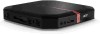

Acer Revo RL70 Desktop Service Guide
Page 6
..., that you should check the most up-to extend the functionality of this generic service guide. For ACER-AUTHORIZED SERVICE PROVIDERS, your Acer office may have decided to -date information available on card, modem, or extra memory capability). These LOCALIZED FEATURES will not be covered in this printed Service Guide. vi If, for...
..., that you should check the most up-to extend the functionality of this generic service guide. For ACER-AUTHORIZED SERVICE PROVIDERS, your Acer office may have decided to -date information available on card, modem, or extra memory capability). These LOCALIZED FEATURES will not be covered in this printed Service Guide. vi If, for...

Acer Revo RL70 Desktop Service Guide
Page 7
... Optical Disc Drive 27 Removing the ODD Base Cover 30 Removing the Sheet Metal 32 Removing the Heat Sink Fan Assembly 33 Removing the Memory Modules 35 Removing the Daughter Board 36 Removing the Wireless LAN Card 37 Removing the Main board 39 Removing the Hard Disk Drive 41... 45 Removing the South Bridge Heat Sink 46 Assembly Requirements 47 Installing the Hard Disk Drive 48 Installing the WLAN Cable 50 Installing the Memory Modules 51 Installing the LED Lens 52 Installing the South Bridge Heat Sink 53 Installing the Antennas of WLAN Card 54 Installing the IR ...
... Optical Disc Drive 27 Removing the ODD Base Cover 30 Removing the Sheet Metal 32 Removing the Heat Sink Fan Assembly 33 Removing the Memory Modules 35 Removing the Daughter Board 36 Removing the Wireless LAN Card 37 Removing the Main board 39 Removing the Hard Disk Drive 41... 45 Removing the South Bridge Heat Sink 46 Assembly Requirements 47 Installing the Hard Disk Drive 48 Installing the WLAN Cable 50 Installing the Memory Modules 51 Installing the LED Lens 52 Installing the South Bridge Heat Sink 53 Installing the Antennas of WLAN Card 54 Installing the IR ...

Acer Revo RL70 Desktop Service Guide
Page 9
...configuration of the computer's many feature: NOTE: The features listed in this section is for your reference only. PCB • 182mm*176mm (Proprietary) Memory subsystem • Socket Type: DDR III SO-DIMM connector • Socket Quantity: 2 • Only support single channel. • Capacity support...: • 1GB / 2 GB DDRIII 1333 SO-DIMM support.(follow AMD Spec.) • 1GB to 4GB Max memory support.(follow AMD Spec.) • Design Criteria: • Should follow AMD Brazos platform design guide. • Should meet AMD Brazos platform design ...
...configuration of the computer's many feature: NOTE: The features listed in this section is for your reference only. PCB • 182mm*176mm (Proprietary) Memory subsystem • Socket Type: DDR III SO-DIMM connector • Socket Quantity: 2 • Only support single channel. • Capacity support...: • 1GB / 2 GB DDRIII 1333 SO-DIMM support.(follow AMD Spec.) • 1GB to 4GB Max memory support.(follow AMD Spec.) • Design Criteria: • Should follow AMD Brazos platform design guide. • Should meet AMD Brazos platform design ...

Acer Revo RL70 Desktop Service Guide
Page 11
... • One D-sub output • Two USB stack *2 • One RJ45 • One DC-in jack • On-board connectors • Two DDRIII SO-DIMM memory sockets. • Two Mini PCIe slot. • 2 audio connector HD. • One SATA sockets (For HDD). • One SATA sockets (For ODD). • One 5V...; Energy Star5.0 support. Chapter 1 3 Buzzer • 1 on chipset BIOS programming guide) Adapter • Universal AC adapter, 90~264V AC, 47~63HZ. • 3-pin 65W with Acer skin • Size: 8Mb(depend on board buzzer.
... • One D-sub output • Two USB stack *2 • One RJ45 • One DC-in jack • On-board connectors • Two DDRIII SO-DIMM memory sockets. • Two Mini PCIe slot. • 2 audio connector HD. • One SATA sockets (For HDD). • One SATA sockets (For ODD). • One 5V...; Energy Star5.0 support. Chapter 1 3 Buzzer • 1 on chipset BIOS programming guide) Adapter • Universal AC adapter, 90~264V AC, 47~63HZ. • 3-pin 65W with Acer skin • Size: 8Mb(depend on board buzzer.

Acer Revo RL70 Desktop Service Guide
Page 15
... Setup Utility Press while the system is booting to enter BIOS Setup Utility. Main Board Major Chips Item Specification Chipset AMD Hudson D1 Super I/O ITE8772 Memory controller AMD Hudson D1 Audio controller Realtek ALC662-VC0-GR LAN controller RealTek 8111E USB controller AMD Hudson D1 Chapter 1 7
... Setup Utility Press while the system is booting to enter BIOS Setup Utility. Main Board Major Chips Item Specification Chipset AMD Hudson D1 Super I/O ITE8772 Memory controller AMD Hudson D1 Audio controller Realtek ALC662-VC0-GR LAN controller RealTek 8111E USB controller AMD Hudson D1 Chapter 1 7

Acer Revo RL70 Desktop Service Guide
Page 16
...,2GB 1GB ~2GB Slot 2 1GB,2GB 1GB ~2GB Maximum System Memory Supported 1GB ~4GB System Memory Item Specification Memory slot number 2 slot Support Memory size per socket 1GB,2GB Support memory type DDR3 SO-DIMM Support memory interface DDR3 1066/1333MHz Support memory voltage 1.35V/1.5V Support memory module package 204-pin DDRIII Support to parity check feature...
...,2GB 1GB ~2GB Slot 2 1GB,2GB 1GB ~2GB Maximum System Memory Supported 1GB ~4GB System Memory Item Specification Memory slot number 2 slot Support Memory size per socket 1GB,2GB Support memory type DDR3 SO-DIMM Support memory interface DDR3 1066/1333MHz Support memory voltage 1.35V/1.5V Support memory module package 204-pin DDRIII Support to parity check feature...

Acer Revo RL70 Desktop Service Guide
Page 19
... this guide display default system values. The system reboots immediately after you close the Setup. Ask a qualified technician for assistance. This memory area is not part of the system RAM which allows configuration data to be retained when power is no need to the CMOS setup...be the same those found in this case, the system cannot retain configuration values in CMOS. The screenshots used in a battery-backed nonvolatile memory called the complementary metaloxide semiconductor (CMOS) Setup Utility. Before you run the CMOS Setup Utility, make changes to run this utility under ...
... this guide display default system values. The system reboots immediately after you close the Setup. Ask a qualified technician for assistance. This memory area is not part of the system RAM which allows configuration data to be retained when power is no need to the CMOS setup...be the same those found in this case, the system cannot retain configuration values in CMOS. The screenshots used in a battery-backed nonvolatile memory called the complementary metaloxide semiconductor (CMOS) Setup Utility. Before you run the CMOS Setup Utility, make changes to run this utility under ...

Acer Revo RL70 Desktop Service Guide
Page 21
... the system. Physical CPU count Total size of the CPU installed on the system. Core speed of system memory installed on the system. Parameter System BIOS Version Build Date Processor Core Frequency Count Memory Size Product Name System Serial Number Asset Tag Number System Date System Time (hh:mm:ss) Description Version...
... the system. Physical CPU count Total size of the CPU installed on the system. Core speed of system memory installed on the system. Parameter System BIOS Version Build Date Processor Core Frequency Count Memory Size Product Name System Serial Number Asset Tag Number System Date System Time (hh:mm:ss) Description Version...
Acer Revo RL70 Desktop Service Guide
Page 24
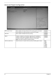
... the additional hardware virtualization capabilities provided by the AMD graphics device. Note: A full reset is required to reduce power consumption. Select the amount of system memory used by this feature allows the OS to change the setting. Advanced Chipset Configuration AMD Cooler'n'Quiet AMD EVP AMD-V UMA Free Buffer Size When...
... the additional hardware virtualization capabilities provided by the AMD graphics device. Note: A full reset is required to reduce power consumption. Select the amount of system memory used by this feature allows the OS to change the setting. Advanced Chipset Configuration AMD Cooler'n'Quiet AMD EVP AMD-V UMA Free Buffer Size When...
Acer Revo RL70 Desktop Service Guide
Page 43
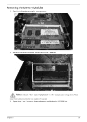
Note:Circuit boards >10 cm² has been highlighted with the yellow rectangle as above image shows. Chapter 3 35 Please detach the Circuit boards and follow local regulations for disposal. 3. Repeat steps 1 and 2 to remove it from the SODIMM2 slot. Gently pull the memory module to remove the second memory module from the SODIMM1 slot. Removing the Memory Modules 1. Open the holding clips securing the memory module. 2.
Note:Circuit boards >10 cm² has been highlighted with the yellow rectangle as above image shows. Chapter 3 35 Please detach the Circuit boards and follow local regulations for disposal. 3. Repeat steps 1 and 2 to remove it from the SODIMM2 slot. Gently pull the memory module to remove the second memory module from the SODIMM1 slot. Removing the Memory Modules 1. Open the holding clips securing the memory module. 2.
Acer Revo RL70 Desktop Service Guide
Page 59
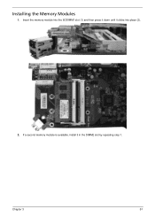
Installing the Memory Modules 1. Chapter 3 51 Insert the memory module into place (2). 2. If a second memory module is available, install it clicks into the SODIMM1 slot (1) and then press it down until it in the DIMM2 slot by repeating step 1.
Installing the Memory Modules 1. Chapter 3 51 Insert the memory module into place (2). 2. If a second memory module is available, install it clicks into the SODIMM1 slot (1) and then press it down until it in the DIMM2 slot by repeating step 1.

Acer Revo RL70 Desktop Service Guide
Page 78
... that occur after the video card has been activated. BIOS damaged. Chapter 4 50 Not all computers using AMIBIOS enable this feature. Memory not installed or memory error. VGA not installed or VGA error. BIOS is damaged, BIOS POST jumps to Boot Block to the end user. CMOS damaged...been initialized. AMIBIOS displays the checkpoints in the bottom right corner of the screen during POST. Graphics card error/not installed, graphics card memory error or graphics card BIOS checksum error. Beep codes will be generated by the BIOS to indicate a serious or fatal error to execute...
... that occur after the video card has been activated. BIOS damaged. Chapter 4 50 Not all computers using AMIBIOS enable this feature. Memory not installed or memory error. VGA not installed or VGA error. BIOS is damaged, BIOS POST jumps to Boot Block to the end user. CMOS damaged...been initialized. AMIBIOS displays the checkpoints in the bottom right corner of the screen during POST. Graphics card error/not installed, graphics card memory error or graphics card BIOS checksum error. Beep codes will be generated by the BIOS to indicate a serious or fatal error to execute...

Acer Revo RL70 Desktop Service Guide
Page 79
...to it only displays checkpoints thatoccur after the video card has been activated. The Bootblock-Runtime interface module is moved to system memory and control is done includingRTC and keyboard controller. CPUID information is currently executing. Checkpoints A checkpoint is either a byte or ... D9 DA Description Early chipset initialization is uncompressed into register. Verify the bootblock checksum. If memory sizing module not executed, start memory refresh and do memory sizingin Bootblock code. BIOS now executes out of the screen during the bootblock initialization portion of...
...to it only displays checkpoints thatoccur after the video card has been activated. The Bootblock-Runtime interface module is moved to system memory and control is done includingRTC and keyboard controller. CPUID information is currently executing. Checkpoints A checkpoint is either a byte or ... D9 DA Description Early chipset initialization is uncompressed into register. Verify the bootblock checksum. If memory sizing module not executed, start memory refresh and do memory sizingin Bootblock code. BIOS now executes out of the screen during the bootblock initialization portion of...
Acer Revo RL70 Desktop Service Guide
Page 91
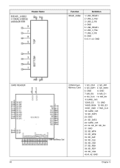
Header Name Function REAR_USB2 Definition 1: USB_REAR1 2: USB_2_FBJ 3: USB_2_FB 4: GND 5: USB_REAR1 6: USB_3_FBJ 7: USB_3_FB 8: GND 9,10,11,12: GND CARD READER 63 CONN-Flash Memory Card 1: SD_CD# 2: SD_WP 3: SD_DAT1 4: SD_DAT0 5: GND 6: GND 7: MS_BS 8: MS_D1 9: SD_CLK 10: MS_D0 11:CARD_3V3 12:MS_D2 13: GND 14:MS_INS# 15: MS_D3 16:SD_CMD 17:MS_CLK 18: CARD_3V3 19 :SD_DAT3 20: GND 21: SD_DAT2 22: CARD_3V3 23~30: XD_D7~XD_D0 31: GND 32: XD_WP# 33: XD_WE# 34: XD_ALE 35: XD_CLE 36: XD_CE# 37: XD_RE# 38: XD_RDY 39: XD_CD# 40,41,42: GND Chapter 5
Header Name Function REAR_USB2 Definition 1: USB_REAR1 2: USB_2_FBJ 3: USB_2_FB 4: GND 5: USB_REAR1 6: USB_3_FBJ 7: USB_3_FB 8: GND 9,10,11,12: GND CARD READER 63 CONN-Flash Memory Card 1: SD_CD# 2: SD_WP 3: SD_DAT1 4: SD_DAT0 5: GND 6: GND 7: MS_BS 8: MS_D1 9: SD_CLK 10: MS_D0 11:CARD_3V3 12:MS_D2 13: GND 14:MS_INS# 15: MS_D3 16:SD_CMD 17:MS_CLK 18: CARD_3V3 19 :SD_DAT3 20: GND 21: SD_DAT2 22: CARD_3V3 23~30: XD_D7~XD_D0 31: GND 32: XD_WP# 33: XD_WE# 34: XD_ALE 35: XD_CLE 36: XD_CE# 37: XD_RE# 38: XD_RDY 39: XD_CD# 40,41,42: GND Chapter 5

Acer Revo RL70 Desktop Service Guide
Page 95
w/rear USBx4, RJ45, VGA/HDMI, SPDIF, w/Y stand for aMerlot Chassis Cooler Memory HDD 67 Chassis uLtraSFF HL110A w/o ODD w/front HS.13100.264 N/A USB2.0x2 w/front CR w/foot stand for aMerlot CCI AMD FT1 18W cooler for Merlot, w/i ... LF+HF F/W:01.01A01 Chapter 6 Revo 70 FRU List Category MB Description Part Number Exploded Diagram Item Mainboard RL70 AMD Hudson D1 Proprietary MB.SJ409.002 9 V1.0 LF ,E450, AMD Radeon HD6320 Mainboard RL70 AMD Hudson D1 Proprietary V1.0 LF ,E300, AMD Radeon HD6310 MB.SJ309.002 Bezel Aspire Bezel AL170 w/o ODD...
w/rear USBx4, RJ45, VGA/HDMI, SPDIF, w/Y stand for aMerlot Chassis Cooler Memory HDD 67 Chassis uLtraSFF HL110A w/o ODD w/front HS.13100.264 N/A USB2.0x2 w/front CR w/foot stand for aMerlot CCI AMD FT1 18W cooler for Merlot, w/i ... LF+HF F/W:01.01A01 Chapter 6 Revo 70 FRU List Category MB Description Part Number Exploded Diagram Item Mainboard RL70 AMD Hudson D1 Proprietary MB.SJ409.002 9 V1.0 LF ,E450, AMD Radeon HD6320 Mainboard RL70 AMD Hudson D1 Proprietary V1.0 LF ,E300, AMD Radeon HD6310 MB.SJ309.002 Bezel Aspire Bezel AL170 w/o ODD...


