

Acer Power SP Service Guide
Page 20
Output Requirements +5V +12V -12V +3.3V +5Vaux +-5% +-5% +-10% +-4% +-5% Regulation NOTE: APSP is equipped with a 200W power supply. 15A 3A 0.3A 12A 3A Current Rating 14 Chapter 1 Switching Power Supply 200W 50MHz 60MHz Input Frequency 47MHz to 53MHz 57MHz to 63MHz Frequency Variation Range Input Voltage 100 - 120 VRMS 200 - 240 VRMS 90 - 132 VRMS 180 - 264 VRMS Variation Range Input Current Measuring Range 4A 90 -132 VRMS 2A 180 - 264 VRMS NOTE: Measure at line input 90 VRMS and maximum load condition.
Output Requirements +5V +12V -12V +3.3V +5Vaux +-5% +-5% +-10% +-4% +-5% Regulation NOTE: APSP is equipped with a 200W power supply. 15A 3A 0.3A 12A 3A Current Rating 14 Chapter 1 Switching Power Supply 200W 50MHz 60MHz Input Frequency 47MHz to 53MHz 57MHz to 63MHz Frequency Variation Range Input Voltage 100 - 120 VRMS 200 - 240 VRMS 90 - 132 VRMS 180 - 264 VRMS Variation Range Input Current Measuring Range 4A 90 -132 VRMS 2A 180 - 264 VRMS NOTE: Measure at line input 90 VRMS and maximum load condition.
Acer Power SP Service Guide
Page 36
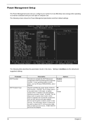
...The S1 sleep mode is to essential components such as Windows 98SE/2000/Me, select Enabled. Settings in which power is supplied only to activate the ACPI (Advanced Configuration and Power Management Interface) Function. S3 (STR): The S3 sleep mode is ACPIaware, such as main memory and wake...-capable devices and all system context. If your operating system is s power-down state in boldface are the default ...
...The S1 sleep mode is to essential components such as Windows 98SE/2000/Me, select Enabled. Settings in which power is supplied only to activate the ACPI (Advanced Configuration and Power Management Interface) Function. S3 (STR): The S3 sleep mode is ACPIaware, such as main memory and wake...-capable devices and all system context. If your operating system is s power-down state in boldface are the default ...

Acer Power SP Service Guide
Page 48
Press the latch and remove the CD-ROM drive. 4. Press the latch and remove the floppy drive. 5. Detach the HDD from the bracket. Removing the Power Supply 1. Press the latch again to release the hard disk module. 6. Remove the power supply. 42 Chapter 3 3. Remove the screws as shown here. 2.
Press the latch and remove the CD-ROM drive. 4. Press the latch and remove the floppy drive. 5. Detach the HDD from the bracket. Removing the Power Supply 1. Press the latch again to release the hard disk module. 6. Remove the power supply. 42 Chapter 3 3. Remove the screws as shown here. 2.

Acer Power SP Service Guide
Page 59
...-connect PS/2 keyboard and mouse. 2. System board 1. System board 1. Enter BIOS Setup and load the default settings. 2. NOTE: Check all power supply voltages, switch, and jumper settings before you did receive a POST error message, use "POST Error Messages List" to replace an FRU, and have...connection. 2. installed, then reboot the system. 1. RTC battery. 4. Remove all adapter cards that are NOT factory- Also check the power supply voltages if you have done so, you have deemed it necessary to diagnose system problems. If you replace the main board. Enter BIOS...
...-connect PS/2 keyboard and mouse. 2. System board 1. System board 1. Enter BIOS Setup and load the default settings. 2. NOTE: Check all power supply voltages, switch, and jumper settings before you did receive a POST error message, use "POST Error Messages List" to replace an FRU, and have...connection. 2. installed, then reboot the system. 1. RTC battery. 4. Remove all adapter cards that are NOT factory- Also check the power supply voltages if you have done so, you have deemed it necessary to diagnose system problems. If you replace the main board. Enter BIOS...

Acer Power SP Service Guide
Page 61
...55 System board. See "Memory" 2. System board. Diskette drive connection/cable 4. Diskette drive 5. Ensure the system is configured correctly in Power Management Property of BIOS Setup. 2. See "Undetermined Problems". Ensure the diskette drive is not set in the Disk Drives of Control Panel. ... Error Symptoms List NOTE: To diagnose a problem, first find the error symptom in chapter 2. 2. System works but power supply fan runs. 1. Insert the memory modules in power saving mode. Reload software from Recovery CD. Enter BIOS Setup and load default settings. Diskette drive...
...55 System board. See "Memory" 2. System board. Diskette drive connection/cable 4. Diskette drive 5. Ensure the system is configured correctly in Power Management Property of BIOS Setup. 2. See "Undetermined Problems". Ensure the diskette drive is not set in the Disk Drives of Control Panel. ... Error Symptoms List NOTE: To diagnose a problem, first find the error symptom in chapter 2. 2. System works but power supply fan runs. 1. Insert the memory modules in power saving mode. Reload software from Recovery CD. Enter BIOS Setup and load default settings. Diskette drive...

Acer Power SP Service Guide
Page 64
.... 1. Reload software from Windows98 Start menu does not turn off the system. (Only pressing power switch can turn off the system.) 1. Power Supply 2. Printing failed. 1. Ensure the printer driver is not running. 1. Ensure the Power Switch < 4 sec. Power switch cable assembly Pressing power switch does not turn on keyboard do not work. 1. Load default settings. 2. System...
.... 1. Reload software from Windows98 Start menu does not turn off the system. (Only pressing power switch can turn off the system.) 1. Power Supply 2. Printing failed. 1. Ensure the printer driver is not running. 1. Ensure the Power Switch < 4 sec. Power switch cable assembly Pressing power switch does not turn on keyboard do not work. 1. Load default settings. 2. System...

Acer Power SP Service Guide
Page 71
....001 MODEM CARD 56K ASKEY 1456VQH75D(INT) MODEM CARD 56K GVC F1156I(+)/R12 /GVC Power Supply POWER SUPPLY 200W W/ O PFC FSP FSP200-ATV POWER SUPPLY 20W W/ PFC FSP FSP200-ATV(PF) Case/Cover/Bracket Assembly FRONT BEZEL W/ POWER BUTTON, 5.25" 3.5" EMPTY COVER, USB DOOR POWER BUTTON USB DOOR SIDE DOOR CHASSIS W/ I/O BRACKET I/O BRACKET RETENTION MODULE LED MODULE FX...
....001 MODEM CARD 56K ASKEY 1456VQH75D(INT) MODEM CARD 56K GVC F1156I(+)/R12 /GVC Power Supply POWER SUPPLY 200W W/ O PFC FSP FSP200-ATV POWER SUPPLY 20W W/ PFC FSP FSP200-ATV(PF) Case/Cover/Bracket Assembly FRONT BEZEL W/ POWER BUTTON, 5.25" 3.5" EMPTY COVER, USB DOOR POWER BUTTON USB DOOR SIDE DOOR CHASSIS W/ I/O BRACKET I/O BRACKET RETENTION MODULE LED MODULE FX...


