

Power FV and Aspire T600 Service Guide
Page 5
... SERVICE PROVIDERS, your Acer office may have decided to extend the functionality of a machine (e.g. This Service Guide provides you with all technical information relating to provide you should check the most up-to-date information available on card, modem, or extra memory capability). In such cases, please contact your regional web or...
... SERVICE PROVIDERS, your Acer office may have decided to extend the functionality of a machine (e.g. This Service Guide provides you with all technical information relating to provide you should check the most up-to-date information available on card, modem, or extra memory capability). In such cases, please contact your regional web or...
Power FV and Aspire T600 Service Guide
Page 6
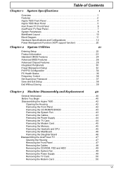
... 1 Overview 1 Features 2 Aspire T600 Front Panel 4 Aspire T600 Rear Panel 5 Acer Power FV Front Panel 6 AcerPower FV Rear Panel 7 System Peripherals 8 MainBoard Layout 10 Block Diagram 11 Hardware Specifications and Configurations 12 Power Management Function (ACPI support function 20 Chapter 2 System Utilities 21 Entering Setup 22 Product.../HDD 43 Removing the System Fan 43 Removing the Cables 43 Removing the Power Supply 44 Removing the TV Card 44 Removing the Modem Card 45 Removing the Memory 45 Removing the Heatsink and CPU 45 Removing the MainBoard 46 Removing the ...
... 1 Overview 1 Features 2 Aspire T600 Front Panel 4 Aspire T600 Rear Panel 5 Acer Power FV Front Panel 6 AcerPower FV Rear Panel 7 System Peripherals 8 MainBoard Layout 10 Block Diagram 11 Hardware Specifications and Configurations 12 Power Management Function (ACPI support function 20 Chapter 2 System Utilities 21 Entering Setup 22 Product.../HDD 43 Removing the System Fan 43 Removing the Cables 43 Removing the Power Supply 44 Removing the TV Card 44 Removing the Modem Card 45 Removing the Memory 45 Removing the Heatsink and CPU 45 Removing the MainBoard 46 Removing the ...

Power FV and Aspire T600 Service Guide
Page 7
Table of Contents Removing the Cables 50 Removing the Memory 50 Removing the Heatsink and CPU 51 Removing the Mainboard 51 Removing the Daughter Board 51 Chapter 4 Troubleshooting 52 Power-On Self-Test (POST 53 POST Error Messages List 59 Error Symptoms List 61 ...Connecting Case Components 69 Connecting Optional Components 72 Chapter 6 FRU (Field Replaceable Unit) List 75 Aspire T600 Exploded Diagram 76 AcerPower FV Exploded Diagram 77 Appendix A Model Definition and Configuration 78 Appendix B Test Compatible Components 79 Microsoft WinXP Home Environment Test 80 ...
Table of Contents Removing the Cables 50 Removing the Memory 50 Removing the Heatsink and CPU 51 Removing the Mainboard 51 Removing the Daughter Board 51 Chapter 4 Troubleshooting 52 Power-On Self-Test (POST 53 POST Error Messages List 59 Error Symptoms List 61 ...Connecting Case Components 69 Connecting Optional Components 72 Chapter 6 FRU (Field Replaceable Unit) List 75 Aspire T600 Exploded Diagram 76 AcerPower FV Exploded Diagram 77 Appendix A Model Definition and Configuration 78 Appendix B Test Compatible Components 79 Microsoft WinXP Home Environment Test 80 ...

Power FV and Aspire T600 Service Guide
Page 9
... Celeron Prescott 775/FSB 533 MHz CPU Socket Type with LGA 775 pins socket Chipset T Northbridge: Intel 915GV T Southbridge: Intel ICH6 Memory T 4 DDR DIMM memory slots (supports up to 4GB memory) T Supports 256Mb/512Mb/1Gb DDR technologies for x8 and x16 non-ECC DDR devices T Supports dual channel DDR 400/333 DIMM T Registered...
... Celeron Prescott 775/FSB 533 MHz CPU Socket Type with LGA 775 pins socket Chipset T Northbridge: Intel 915GV T Southbridge: Intel ICH6 Memory T 4 DDR DIMM memory slots (supports up to 4GB memory) T Supports 256Mb/512Mb/1Gb DDR technologies for x8 and x16 non-ECC DDR devices T Supports dual channel DDR 400/333 DIMM T Registered...

Power FV and Aspire T600 Service Guide
Page 10
...Parallel Port, 1 Serial Port T 1 VGA Port T 1 LAN Port T 4 USB Ports T 6 Ports Jack Support HD audio output T On-board Connectors T 1 CPU Socket T 4 Memory DIMM T 1 PCI Express x1 Slot T 1 FDD Slot T 1 PATA IDE Slot T 2 SATA IDE Slots T 1 2*5 pin Intel FPIO Specification USB pin Connectors T 2 1*5 pin ...T 1 3pin or 4 pin CPU Fan Connector T 1 24pin and 4 pin ATX Interface PS3/PS2 SPS Connector T 1 2*4pin Intel FPIO Specification Power Switch/Power State T LED/HDD Active LED T 1 2pin LAN Activity Monitor Connector T 2 Reserved 2pin GPIO Connector T Color Management for On Board Connector Chapter...
...Parallel Port, 1 Serial Port T 1 VGA Port T 1 LAN Port T 4 USB Ports T 6 Ports Jack Support HD audio output T On-board Connectors T 1 CPU Socket T 4 Memory DIMM T 1 PCI Express x1 Slot T 1 FDD Slot T 1 PATA IDE Slot T 2 SATA IDE Slots T 1 2*5 pin Intel FPIO Specification USB pin Connectors T 2 1*5 pin ...T 1 3pin or 4 pin CPU Fan Connector T 1 24pin and 4 pin ATX Interface PS3/PS2 SPS Connector T 1 2*4pin Intel FPIO Specification Power Switch/Power State T LED/HDD Active LED T 1 2pin LAN Activity Monitor Connector T 2 Reserved 2pin GPIO Connector T Color Management for On Board Connector Chapter...
Power FV and Aspire T600 Service Guide
Page 19
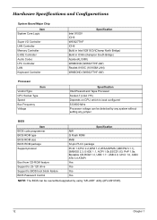
Hardware Specifications and Configurations System Board Major Chip Item System Core Logic Super I/O Controller LAN Controller Memory Controller E-IDE Controller Audio Codec LPC Controller LAN Keyboard Controller Specification Intel 915GV ICH6 W83627THF ICH6 Build in Intel 82915GV(Champ North Bridge) Build in ...
Hardware Specifications and Configurations System Board Major Chip Item System Core Logic Super I/O Controller LAN Controller Memory Controller E-IDE Controller Audio Codec LPC Controller LAN Keyboard Controller Specification Intel 915GV ICH6 W83627THF ICH6 Build in Intel 82915GV(Champ North Bridge) Build in ...
Power FV and Aspire T600 Service Guide
Page 20
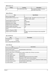
...BIOS Setup L2 Cache scheme Fixed in write-back Chapter 1 13 System Memory Item Memory Slot(s) Number Supported Memory Size per Slot Supported Maximum Memory Size Supported Memory Speed Supported memory voltage Support memory module package Support to parity check feature Support to Error Correction Code (... 400MHz Bus Architecture Item PCI Express 1X 1 PCS PCI Slot 3 PCS LAN on Board REALTEK RTL8100C Description Cache Memory Item Specification First-Level Cache Configurations Cache function control Enable/Disable by BIOS Setup Second-Level Cache Configurations The information ...
...BIOS Setup L2 Cache scheme Fixed in write-back Chapter 1 13 System Memory Item Memory Slot(s) Number Supported Memory Size per Slot Supported Maximum Memory Size Supported Memory Speed Supported memory voltage Support memory module package Support to parity check feature Support to Error Correction Code (... 400MHz Bus Architecture Item PCI Express 1X 1 PCS PCI Slot 3 PCS LAN on Board REALTEK RTL8100C Description Cache Memory Item Specification First-Level Cache Configurations Cache function control Enable/Disable by BIOS Setup Second-Level Cache Configurations The information ...

Power FV and Aspire T600 Service Guide
Page 22
System LED Definition LED Power State LED S0 S1/S3 S4/S5 HDD State LED ... Onboard System ROM BIOS (ROM) System RAM BIOS (DRAM) Chapter 1 15 Max. Legacy Keyboard and Mouse support Memory Address Map Address 0000000 - 009FFFF 00A0000-00BFFFF 00C0000-00CFFFF 00D0000-00D3FFF 00D4000-00D7FFF 00D8000-00DBFFF 00DC000-00DFFFF 00E0000-00E7FFF 00E8000...-00EFFFF 00F0000-00FFFFF Size 640 KB System Memory 128 KB Video RAM 32 KB I/O Expansion ROM 16 KB I/O Expansion ROM 16 KB I/O Expansion ROM 16 ...
System LED Definition LED Power State LED S0 S1/S3 S4/S5 HDD State LED ... Onboard System ROM BIOS (ROM) System RAM BIOS (DRAM) Chapter 1 15 Max. Legacy Keyboard and Mouse support Memory Address Map Address 0000000 - 009FFFF 00A0000-00BFFFF 00C0000-00CFFFF 00D0000-00D3FFF 00D4000-00D7FFF 00D8000-00DBFFF 00DC000-00DFFFF 00E0000-00E7FFF 00E8000...-00EFFFF 00F0000-00FFFFF Size 640 KB System Memory 128 KB Video RAM 32 KB I/O Expansion ROM 16 KB I/O Expansion ROM 16 KB I/O Expansion ROM 16 ...

Power FV and Aspire T600 Service Guide
Page 23
... dual channel technology, the bandwidth of Intel chipset specifications. NOTE: We strongly recommend user to the limitation of memory bus will not operate installed ? Aspire T600/AcerPower FV inculde 4 DIMM sockets, and each channel has two DIMM sockets as following tables include all... memory-installed combination types: Dual Channel Technology (DS: Double Side, SS: Single Side) 2 memory modules 4 memory modules DDR1 DS/SS X DS/SS DDR2 ...
... dual channel technology, the bandwidth of Intel chipset specifications. NOTE: We strongly recommend user to the limitation of memory bus will not operate installed ? Aspire T600/AcerPower FV inculde 4 DIMM sockets, and each channel has two DIMM sockets as following tables include all... memory-installed combination types: Dual Channel Technology (DS: Double Side, SS: Single Side) 2 memory modules 4 memory modules DDR1 DS/SS X DS/SS DDR2 ...

Power FV and Aspire T600 Service Guide
Page 35
The value is set at the default value. The 3T setting requires faster memory that the item would be hidden when set Configure DRAM Timing by SPD Enables you insert a timing delay between ...be hidden when set Configure DRAM Timing by SPD to select the CAS latency time in the computer. These registers control most of DRAM memory CAS (column address strobe). DRAM RAS# to CAS# Delay This field lets you to Enabled. 28 Chapter 2 and Enabled gives more... Configure DRAM Timing by SPD to , read from, or refreshed. Please be noted that you change specifications of DRAM memory.
The value is set at the default value. The 3T setting requires faster memory that the item would be hidden when set Configure DRAM Timing by SPD Enables you insert a timing delay between ...be hidden when set Configure DRAM Timing by SPD to select the CAS latency time in the computer. These registers control most of DRAM memory CAS (column address strobe). DRAM RAS# to CAS# Delay This field lets you to Enabled. 28 Chapter 2 and Enabled gives more... Configure DRAM Timing by SPD to , read from, or refreshed. Please be noted that you change specifications of DRAM memory.

Power FV and Aspire T600 Service Guide
Page 36
...to a section of the PCI slots or is integrated on the mainboard This item shows the VGA memory size borrowed from main memory capacity. Parameter Init Display First VGA Share Memory Aperture Size Select PEG Port Description Use this item at the default value. The AGP aperture refers to... specify whether your graphics adapter is installed in one of the PCI memory address range used for graphics memory. This item enables or disables ...
...to a section of the PCI slots or is integrated on the mainboard This item shows the VGA memory size borrowed from main memory capacity. Parameter Init Display First VGA Share Memory Aperture Size Select PEG Port Description Use this item at the default value. The AGP aperture refers to... specify whether your graphics adapter is installed in one of the PCI memory address range used for graphics memory. This item enables or disables ...

Power FV and Aspire T600 Service Guide
Page 39
S3 (STR): The S3 sleep mode is s power-down state in memory will be used to restore the PC to power off. Instand-off : Press down button then power off by PWR-BTTN Description Options This item specifies the power saving modes for ACPI function. Enter suspend if button is saved to essential ... is pressed less than 4 sec. 32 Chapter 2 Disabled 1~15 Mins This feature allows users to S1/POS(Power On Suspend). The information stored in which power is supplied only to main memory. to the previous state when an wake-up event occurs. S1(POS): The S1 sleep mode is independent from...
S3 (STR): The S3 sleep mode is s power-down state in memory will be used to restore the PC to power off. Instand-off : Press down button then power off by PWR-BTTN Description Options This item specifies the power saving modes for ACPI function. Enter suspend if button is saved to essential ... is pressed less than 4 sec. 32 Chapter 2 Disabled 1~15 Mins This feature allows users to S1/POS(Power On Suspend). The information stored in which power is supplied only to main memory. to the previous state when an wake-up event occurs. S1(POS): The S1 sleep mode is independent from...

Power FV and Aspire T600 Service Guide
Page 44
... the selection. Chapter 2 37 Type the password, up to enter password. Once the password is selected, the following message appears at "Security Option" from CMOS memory. The password typed now will confirm the password being disabled. To disable password, just press when you have selected "Setup" at the center of "BIOS...
... the selection. Chapter 2 37 Type the password, up to enter password. Once the password is selected, the following message appears at "Security Option" from CMOS memory. The password typed now will confirm the password being disabled. To disable password, just press when you have selected "Setup" at the center of "BIOS...

Power FV and Aspire T600 Service Guide
Page 52
Then remove it as shown here, pull out the modem card. Chapter 3 45 Remove the screws as shown here. . Removing the Heatsink and CPU 1. Remove the four screws as shown here, then remove heatsink module. 2. Pull out the memory1, memory2, memory3 and memory4. Removing the Modem Card 1. Removing the Memory 1. Pull the CPU bar up to 90 degrees and remove the CPU then press down the CPU bar to the end.
Then remove it as shown here, pull out the modem card. Chapter 3 45 Remove the screws as shown here. . Removing the Heatsink and CPU 1. Remove the four screws as shown here, then remove heatsink module. 2. Pull out the memory1, memory2, memory3 and memory4. Removing the Modem Card 1. Removing the Memory 1. Pull the CPU bar up to 90 degrees and remove the CPU then press down the CPU bar to the end.

Power FV and Aspire T600 Service Guide
Page 57
Remove the screws as shown here, pull out the modem card. Removing the Modem Card Remove the screws as shown here. Disconnect the Serial ATA cable. 3. Pull out the CD-IN from TV card. 2. Removing the Cables 1. Removing the Memory Remove the four screws as shown here, then remove heatsink module. 50 Chapter 3 then pull out the TV card. Removing the TV Card 1. Disconnect the USB Cable. 2. Disconnect the Audio Cable.
Remove the screws as shown here, pull out the modem card. Removing the Modem Card Remove the screws as shown here. Disconnect the Serial ATA cable. 3. Pull out the CD-IN from TV card. 2. Removing the Cables 1. Removing the Memory Remove the four screws as shown here, then remove heatsink module. 50 Chapter 3 then pull out the TV card. Removing the TV Card 1. Disconnect the USB Cable. 2. Disconnect the Audio Cable.

Power FV and Aspire T600 Service Guide
Page 60
...Xgroup codes locating in the table, refer to the corresponding product service guide. If POST discovers errors in numeric co-processor and cache memory subsystem T Direct Memory Access (DMA) controller T Interrupt system T Three programmable timers T ROM subsystem T RAM subsystem T CMOS RAM subsystem and real time...-Disable shadow RAM -Disable L2 cache (socket 7 or below) -Program basic chipset registers Detect memory -Auto-detection of DRAM size, type and ECC. -Auto-detection of the power-on password option. The main components on the main board that boots the system, initializes and ...
...Xgroup codes locating in the table, refer to the corresponding product service guide. If POST discovers errors in numeric co-processor and cache memory subsystem T Direct Memory Access (DMA) controller T Interrupt system T Three programmable timers T ROM subsystem T RAM subsystem T CMOS RAM subsystem and real time...-Disable shadow RAM -Disable L2 cache (socket 7 or below) -Program basic chipset registers Detect memory -Auto-detection of DRAM size, type and ECC. -Auto-detection of the power-on password option. The main components on the main board that boots the system, initializes and ...

Power FV and Aspire T600 Service Guide
Page 62
...CPU. 3. Invoke video BIOS. Reserved Reserved Reserved Reserved Reserved Reset keyboard except Winbond 977 series Super I /O resource -Search for 0-640K memory address. 2. Reserved Reserved Reserved Reserved Reserved Reserved Reserved Reserved 55 Chapter 4 Program CPU internal MTRR (P6 & PII) for a valid VGA... multi-language 2. Load CMOS settings into consideration of the ESCD's legacy information. 4. Early PCI initialization -Enumerate PCI bus number -Assign memory & I /O chips. Checkpoint 23h 24h 25h 26h 27h 28h 29h 2Ah 2Bh 2Ch 2Dh 2Eh 2Fh 30h 31h 32h 33h 34h 35h...
...CPU. 3. Invoke video BIOS. Reserved Reserved Reserved Reserved Reserved Reset keyboard except Winbond 977 series Super I /O resource -Search for 0-640K memory address. 2. Reserved Reserved Reserved Reserved Reserved Reserved Reserved Reserved 55 Chapter 4 Program CPU internal MTRR (P6 & PII) for a valid VGA... multi-language 2. Load CMOS settings into consideration of the ESCD's legacy information. 4. Early PCI initialization -Enumerate PCI bus number -Assign memory & I /O chips. Checkpoint 23h 24h 25h 26h 27h 28h 29h 2Ah 2Bh 2Ch 2Dh 2Eh 2Fh 30h 31h 32h 33h 34h 35h...

Power FV and Aspire T600 Service Guide
Page 63
... MP platform, adjust the cacheable range to smaller one in case the cacheable ranges between each 64K. 2. Reserved Initialize USB Reserved Test all memory (clear all extended memory to every ISA PnP device. . Checkpoint 3Ch 3Dh 3Eh 3Fh 40h 41h 42h 43h 44h 45h 46h 47h 48h 49h 4Ah 4Bh 4Ch 4Dh... 55h 56h 57h 58h 59h 5Ah 5Bh 5Ch Description Test 8254. Reserved Reserved Reserved Reserved 1. Program MTRR of each CPU are not identical. Calculate total memory by testing the last double word of M1 CPU. 2.
... MP platform, adjust the cacheable range to smaller one in case the cacheable ranges between each 64K. 2. Reserved Initialize USB Reserved Test all memory (clear all extended memory to every ISA PnP device. . Checkpoint 3Ch 3Dh 3Eh 3Fh 40h 41h 42h 43h 44h 45h 46h 47h 48h 49h 4Ah 4Bh 4Ch 4Dh... 55h 56h 57h 58h 59h 5Ah 5Bh 5Ch Description Test 8254. Reserved Reserved Reserved Reserved 1. Program MTRR of each CPU are not identical. Calculate total memory by testing the last double word of M1 CPU. 2.

Power FV and Aspire T600 Service Guide
Page 64
... related fields in floppy drive -ALT+F2 is set to enter Setup utility; Initialize Init_Onboard_Super_IO switch. 2. Reserved Reserved Reserved Reserved Initialize PS/2 Mouse Reserved Prepare memory size information for function call: INT 15h ax=E820h Reserved Turn on L2 cache Reserved Program chipset registers according to all IDE devices: HDD, LS120...
... related fields in floppy drive -ALT+F2 is set to enter Setup utility; Initialize Init_Onboard_Super_IO switch. 2. Reserved Reserved Reserved Reserved Initialize PS/2 Mouse Reserved Prepare memory size information for function call: INT 15h ax=E820h Reserved Turn on L2 cache Reserved Program chipset registers according to all IDE devices: HDD, LS120...

Power FV and Aspire T600 Service Guide
Page 65
...used by EPA logo (not for Trend Anti-Virus code 1. USB final Initialization 2. Chipset final initialization 4. Program daylight saving 2. Call chipset power management hook. 2. If password is pressed to text mode if full screen logo is supported. -If errors occur, report errors & wait ... errors occur or F1 key is set, ask for password. Initialize ISA PnP boot devices. 1. Set up speed 3. Clear noise of memory. 5. Power management final initialization 5. Build MP table 2. Load CMOS time into DOS timer tick 5. Reserved Reserved 1. Program boot up ACPI table at...
...used by EPA logo (not for Trend Anti-Virus code 1. USB final Initialization 2. Chipset final initialization 4. Program daylight saving 2. Call chipset power management hook. 2. If password is pressed to text mode if full screen logo is supported. -If errors occur, report errors & wait ... errors occur or F1 key is set, ask for password. Initialize ISA PnP boot devices. 1. Set up speed 3. Clear noise of memory. 5. Power management final initialization 5. Build MP table 2. Load CMOS time into DOS timer tick 5. Reserved Reserved 1. Program boot up ACPI table at...


