

Service Guide
Page 5
......2 System Block Diagram ...6 Optics Conceptual Drawing 7 Chapter 2 Firmware Update 8 Setup Tool / Equipment...8 Upgrading Procedure ...8 Chapter 3 Machine Dissassembly and Replacement 10 General Information ...11 Disassemble Lamp Module 12 Disassemble IO Cover & Top Cover 13 Disassemble Speaker & Front Cover 14 Disassemble Front Fan...15 Disassemble Front IR Board & IR Cover 16 Disassemble ...
......2 System Block Diagram ...6 Optics Conceptual Drawing 7 Chapter 2 Firmware Update 8 Setup Tool / Equipment...8 Upgrading Procedure ...8 Chapter 3 Machine Dissassembly and Replacement 10 General Information ...11 Disassemble Lamp Module 12 Disassemble IO Cover & Top Cover 13 Disassemble Speaker & Front Cover 14 Disassemble Front Fan...15 Disassemble Front IR Board & IR Cover 16 Disassemble ...

Service Guide
Page 8
SYSTEM SPECIFICATIONS 2.1 Driver conditions See driver specifications for more information EUC 200V/01 * If the lamp voltage is below 35V continued over 90s, the driver shuts down. ** If the lamp voltage reaches over 140V, the driver shuts down immediately. 2.2 Run-up time Run-up -...no cooling of a short arc burner in a reflector, and a lamp driver. Cooling of these ignition failures may occur subsequently. Lamp Specification 1.Product Scope The product is a lamp system consisting of the burner recommended. Lamp type UHP 200W-150W 1.0 Driver type EUC 200V/01 TopValue 2. During...
SYSTEM SPECIFICATIONS 2.1 Driver conditions See driver specifications for more information EUC 200V/01 * If the lamp voltage is below 35V continued over 90s, the driver shuts down. ** If the lamp voltage reaches over 140V, the driver shuts down immediately. 2.2 Run-up time Run-up -...no cooling of a short arc burner in a reflector, and a lamp driver. Cooling of these ignition failures may occur subsequently. Lamp Specification 1.Product Scope The product is a lamp system consisting of the burner recommended. Lamp type UHP 200W-150W 1.0 Driver type EUC 200V/01 TopValue 2. During...

Service Guide
Page 9
..., Philips recommends to: Avoid twisted cables Never tie the cables together Avoid contact to conductive plates, especially if those are connected to keep the lamp burning for at least 15 minutes. bulb temperature of 300 oC+ -25oC : 98% ignition reliability of the total number of the electrodes. ... have to be applied 15 seconds after shut down. It is known that asymmetric cooling after switching the lamp off, can be repeated up to max. 5 times, if the lamp has not successfully started from earthed mounting screws to hazardous voltage traces on 1 of switches. Philips suggests ...
..., Philips recommends to: Avoid twisted cables Never tie the cables together Avoid contact to conductive plates, especially if those are connected to keep the lamp burning for at least 15 minutes. bulb temperature of 300 oC+ -25oC : 98% ignition reliability of the total number of the electrodes. ... have to be applied 15 seconds after shut down. It is known that asymmetric cooling after switching the lamp off, can be repeated up to max. 5 times, if the lamp has not successfully started from earthed mounting screws to hazardous voltage traces on 1 of switches. Philips suggests ...

Service Guide
Page 10
3 LAMP SPECIFICATIONS 3.1 Dimensions Reflector type E19 3 Average lamp life and lumen maintenance (on test & operational conditions see 4.4 and based upon a large sample population) When driven at 200W on ballast type EUC 200V/01 and temperature conditions are fulfilled (AN 2002-002) > 85% 500h > 50% 2000h According to the light specification table (see paragraph 4.5.2) When driven at 150W on ballast type EUC 200V/01 and temperature conditions are fulfilled (AN 2002-002) > 85% 500h > 50% 2500h According to the light specification table (see paragraph 4.5.2) Chapter 1 4
3 LAMP SPECIFICATIONS 3.1 Dimensions Reflector type E19 3 Average lamp life and lumen maintenance (on test & operational conditions see 4.4 and based upon a large sample population) When driven at 200W on ballast type EUC 200V/01 and temperature conditions are fulfilled (AN 2002-002) > 85% 500h > 50% 2000h According to the light specification table (see paragraph 4.5.2) When driven at 150W on ballast type EUC 200V/01 and temperature conditions are fulfilled (AN 2002-002) > 85% 500h > 50% 2500h According to the light specification table (see paragraph 4.5.2) Chapter 1 4
Service Guide
Page 11
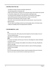
.... - The screw, which connects the cable with bare hands. Visible arc instability has to be suppressed by set maker must design a lamp house to notify the customer that obliges the visible notification on the reflector of in paragraph 1. - For more information about Hg marking, check... To comply in accordance with destination USA needs to keep glass pieces in case it should be cleaned with national regulations/law. To replace the lamp, the power should be switched off ). - Never touch the burner or reflector mirror with the side connector, may not touch the reflector surface. -...
.... - The screw, which connects the cable with bare hands. Visible arc instability has to be suppressed by set maker must design a lamp house to notify the customer that obliges the visible notification on the reflector of in paragraph 1. - For more information about Hg marking, check... To comply in accordance with destination USA needs to keep glass pieces in case it should be cleaned with national regulations/law. To replace the lamp, the power should be switched off ). - Never touch the burner or reflector mirror with the side connector, may not touch the reflector surface. -...
Service Guide
Page 18
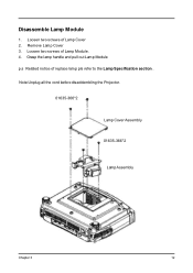
Remove Lamp Cover 3. Loosen two screws of replace lamp pls refer to the Lamp Specification section . Grasp the lamp handle and pull out Lamp Module p.s Related notice of Lamp Module . 4. Disassemble Lamp Module 1. Loosen two screws of Lamp Cover 2. Note:Unplug all the cord before disaddembling the Projector. 01635-366*2 Lamp Cover Assembly 01635-366*2 Lam p Assem bly Chapter 3 12
Remove Lamp Cover 3. Loosen two screws of replace lamp pls refer to the Lamp Specification section . Grasp the lamp handle and pull out Lamp Module p.s Related notice of Lamp Module . 4. Disassemble Lamp Module 1. Loosen two screws of Lamp Cover 2. Note:Unplug all the cord before disaddembling the Projector. 01635-366*2 Lamp Cover Assembly 01635-366*2 Lam p Assem bly Chapter 3 12
Service Guide
Page 37
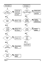
Fail to light up No Volume Check LED indication OK Look up user NG manual ,and follow indica- tive action Check Lamp NG Replace Lamp Check Top cover's cable NG Replace cable or connect the cable back OK Check Speaker Connector NG Speaker Connector Become loose OK Check Thermal Sensor NG Replace Ther- mal Sensor OK Check Speaker NG Replace Speaker OK OK Check Fan NG Replace Fan OK Check Main Board NG Replace Main Board Check Main Board OK Replace Main OK Check Ballast NG Replace Ballast Chapter 4 32
Fail to light up No Volume Check LED indication OK Look up user NG manual ,and follow indica- tive action Check Lamp NG Replace Lamp Check Top cover's cable NG Replace cable or connect the cable back OK Check Speaker Connector NG Speaker Connector Become loose OK Check Thermal Sensor NG Replace Ther- mal Sensor OK Check Speaker NG Replace Speaker OK OK Check Fan NG Replace Fan OK Check Main Board NG Replace Main Board Check Main Board OK Replace Main OK Check Ballast NG Replace Ballast Chapter 4 32

Service Guide
Page 40
Power Source: No Power Source After Turning On Fan failure After Turning On Check Lamp Cover Switch OK Check Power Cord OK Check Top Cover (key cable..) NG Replace Lamp Cover or Reassembly NG Replace Power Cord NG Replace cable or key Check Fan Connector OK Check Inner Wires OK Check Fan NG Fan Connector Become loose NG Replace Inner Wires NG Replace Fan OK Check Main Board OK Check Power Board NG Replace Main Board OK Check Main Board OK NG Replace Main Board NG Replace Power Board Replace Power Baord OK Replace Standby Signal cable NG 35 Chapter 4
Power Source: No Power Source After Turning On Fan failure After Turning On Check Lamp Cover Switch OK Check Power Cord OK Check Top Cover (key cable..) NG Replace Lamp Cover or Reassembly NG Replace Power Cord NG Replace cable or key Check Fan Connector OK Check Inner Wires OK Check Fan NG Fan Connector Become loose NG Replace Inner Wires NG Replace Fan OK Check Main Board OK Check Power Board NG Replace Main Board OK Check Main Board OK NG Replace Main Board NG Replace Power Board Replace Power Baord OK Replace Standby Signal cable NG 35 Chapter 4

Service Guide
Page 54
Ballaster Board Summarize Connector X1 X2 X3 P o w e r input S C I & F lag Connection to lamp Description The Locations of Connectors X1 : Power input PIN# 1 3 X2: SCI & Flag PIN# 1 2 3 4 5 X3: Connection to lamp PIN# 1 4 49 Description D C Input voltage GND Description Flag/TxD (coll.) Flag/TxD (emitter) Common+ (anodes) S C I/Sync (cath.) RxD (cath.) Description LAMP LAMP Chapter 5
Ballaster Board Summarize Connector X1 X2 X3 P o w e r input S C I & F lag Connection to lamp Description The Locations of Connectors X1 : Power input PIN# 1 3 X2: SCI & Flag PIN# 1 2 3 4 5 X3: Connection to lamp PIN# 1 4 49 Description D C Input voltage GND Description Flag/TxD (coll.) Flag/TxD (emitter) Common+ (anodes) S C I/Sync (cath.) RxD (cath.) Description LAMP LAMP Chapter 5


