

Service Guide
Page 3
Gives precautionary measures to avoid possible hardware or software problems. Reminds you to any damage that appear on screen. Conventions The following conventions are used in this manual Screen messages Denotes actual messages that might result from doing or not doing specific actions. Note Warning Caution Important Gives bits and pieces of additional information related to the accomplishment of procedures. Alerts you to do specific actions relevant to the current topic.
Gives precautionary measures to avoid possible hardware or software problems. Reminds you to any damage that appear on screen. Conventions The following conventions are used in this manual Screen messages Denotes actual messages that might result from doing or not doing specific actions. Note Warning Caution Important Gives bits and pieces of additional information related to the accomplishment of procedures. Alerts you to do specific actions relevant to the current topic.

Service Guide
Page 4
... be noted in the printed Service Guide. This Service Guide provides you with all technical information relating to order FRU parts for repair and service of a machine (e.g. To better fit local market requirements and enhance product competitiveness, your regional Acer office to the BASIC CONFIGURATION decided for whatever reason, apart number change is made, it supports, please read the following general...
... be noted in the printed Service Guide. This Service Guide provides you with all technical information relating to order FRU parts for repair and service of a machine (e.g. To better fit local market requirements and enhance product competitiveness, your regional Acer office to the BASIC CONFIGURATION decided for whatever reason, apart number change is made, it supports, please read the following general...

Service Guide
Page 5
... Contents Chapter 1 System Introduction 1 Technical Specification ...1 Lamp Specification...2 System Block Diagram ...6 Optics Conceptual Drawing 7 Chapter 2 Firmware Update 8 Setup Tool / Equipment...8 Upgrading Procedure ...8 Chapter 3 Machine Dissassembly and Replacement 10 General Information ...11 Disassemble Lamp Module 12 Disassemble IO Cover & Top Cover 13 Disassemble Speaker & Front Cover 14 Disassemble Front Fan...15 Disassemble Front IR Board & IR Cover 16 Disassemble Video IO ...17 Dissassemble Main Board 18...
... Contents Chapter 1 System Introduction 1 Technical Specification ...1 Lamp Specification...2 System Block Diagram ...6 Optics Conceptual Drawing 7 Chapter 2 Firmware Update 8 Setup Tool / Equipment...8 Upgrading Procedure ...8 Chapter 3 Machine Dissassembly and Replacement 10 General Information ...11 Disassemble Lamp Module 12 Disassemble IO Cover & Top Cover 13 Disassemble Speaker & Front Cover 14 Disassemble Front Fan...15 Disassemble Front IR Board & IR Cover 16 Disassemble Video IO ...17 Dissassemble Main Board 18...

Service Guide
Page 6
Table of Contents Chapter 4 Trouble shooting 30 Video Signal troubleshooting 31 Operation FunctionTroubleshooting 34 Power SourceTroubleshooting 35 Function Test and Alignment 36 Equipment Needed 36 Test Condition...36 Test Display Modes and Patterns 37 Compatible Modes 37 Function Test Display Pattern 38 Chapter 5 Connector Information 40 Introduction...40 Main Board...40 Power Board ...46 Ballast Board ...48 Chapter 6 FRU(FieldReplaceable Unit) List 49 FRU List...50
Table of Contents Chapter 4 Trouble shooting 30 Video Signal troubleshooting 31 Operation FunctionTroubleshooting 34 Power SourceTroubleshooting 35 Function Test and Alignment 36 Equipment Needed 36 Test Condition...36 Test Display Modes and Patterns 37 Compatible Modes 37 Function Test Display Pattern 38 Chapter 5 Connector Information 40 Introduction...40 Main Board...40 Power Board ...46 Ballast Board ...48 Chapter 6 FRU(FieldReplaceable Unit) List 49 FRU List...50

Service Guide
Page 9
... ground (e.g. bulb temperature of 300 oC+ -25oC : 99.9% ignition reliability of the total number of switches. Philips suggests after a successful starting attempt to keep the cables straightened having a mutual distance (of the system can be given to the distances from the first time. Special consideration has to be repeated up to max. 5 times, if the lamp has not successfully started from earthed mounting screws to...
... ground (e.g. bulb temperature of 300 oC+ -25oC : 99.9% ignition reliability of the total number of switches. Philips suggests after a successful starting attempt to keep the cables straightened having a mutual distance (of the system can be given to the distances from the first time. Special consideration has to be repeated up to max. 5 times, if the lamp has not successfully started from earthed mounting screws to...
Service Guide
Page 11
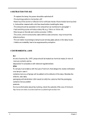
To replace the lamp, the power should be operated on 10min off . - The screw, which connects the cable with bare hands. Never touch the burner or reflector mirror with the side connector, may not touch the reflector surface. - The lamp should be cleaned with destination USA needs to notify the customer that obliges the visible notification on a lamp in the lamp house...
To replace the lamp, the power should be operated on 10min off . - The screw, which connects the cable with bare hands. Never touch the burner or reflector mirror with the side connector, may not touch the reflector surface. - The lamp should be cleaned with destination USA needs to notify the customer that obliges the visible notification on a lamp in the lamp house...

Service Guide
Page 14
Open burning programma (DLP Composer Lite) Chapter 2 8 USB Cable (see right picture) 3. Connect Download Cable to projector 2. Power Coard Upgrading Procedure 1. Chapter 2 Firmware Upgrade This chapter provides the equipment needed, setup and upgrading procedure for Firmware upgrade. Computer 2. Setup Tool / Equipment 1.
Open burning programma (DLP Composer Lite) Chapter 2 8 USB Cable (see right picture) 3. Connect Download Cable to projector 2. Power Coard Upgrading Procedure 1. Chapter 2 Firmware Upgrade This chapter provides the equipment needed, setup and upgrading procedure for Firmware upgrade. Computer 2. Setup Tool / Equipment 1.
Service Guide
Page 15
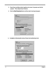
Completion of program . 5. 3. Than release these 2 bottoms . 4. Press Power and Menu button together and connect the power cord into the projector . Click the Start Download button and then start to burning of Burning than remove Power Cord and Burning Cord . 9 Chapter 2
Completion of program . 5. 3. Than release these 2 bottoms . 4. Press Power and Menu button together and connect the power cord into the projector . Click the Start Download button and then start to burning of Burning than remove Power Cord and Burning Cord . 9 Chapter 2
Service Guide
Page 16
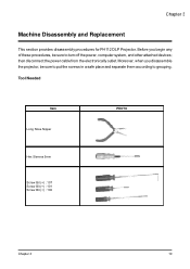
Tool Needed Item Long Nose Nipper Hex Sleeves 5mm Screw Bit (+) : 107 Screw Bit (+) : 101 Screw Bit (+) : 102 PHOTO Chapter 3 10 Moreover, when you begin any of these procedures, be sure to put the screws in a safe place and separate them according to turn off the power, computer system, and other attached devices; Chapter 3 Machine Disassembly and Replacement This section provides disassembly procedures for PH112 DLP Projector. then disconnect the power cable from the electronically outlet. Before you disassemble the projector, be sure to grouping.
Tool Needed Item Long Nose Nipper Hex Sleeves 5mm Screw Bit (+) : 107 Screw Bit (+) : 101 Screw Bit (+) : 102 PHOTO Chapter 3 10 Moreover, when you begin any of these procedures, be sure to put the screws in a safe place and separate them according to turn off the power, computer system, and other attached devices; Chapter 3 Machine Disassembly and Replacement This section provides disassembly procedures for PH112 DLP Projector. then disconnect the power cable from the electronically outlet. Before you disassemble the projector, be sure to grouping.

Service Guide
Page 17
Turn off the power to the system and all power and signal cables from the system. 3. Wear Anti-static wrist strap. 11 Chapter 3 Unplug the AC adapter and all peripherals. 2. General Information Before You Begin Before proceeding with the disassembly procedure, make sure that you do the following: 1.
Turn off the power to the system and all power and signal cables from the system. 3. Wear Anti-static wrist strap. 11 Chapter 3 Unplug the AC adapter and all peripherals. 2. General Information Before You Begin Before proceeding with the disassembly procedure, make sure that you do the following: 1.
Service Guide
Page 18
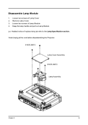
Loosen two screws of replace lamp pls refer to the Lamp Specification section . Disassemble Lamp Module 1. Grasp the lamp handle and pull out Lamp Module p.s Related notice of Lamp Module . 4. Note:Unplug all the cord before disaddembling the Projector. 01635-366*2 Lamp Cover Assembly 01635-366*2 Lam p Assem bly Chapter 3 12 Remove Lamp Cover 3. Loosen two screws of Lamp Cover 2.
Loosen two screws of replace lamp pls refer to the Lamp Specification section . Disassemble Lamp Module 1. Grasp the lamp handle and pull out Lamp Module p.s Related notice of Lamp Module . 4. Note:Unplug all the cord before disaddembling the Projector. 01635-366*2 Lamp Cover Assembly 01635-366*2 Lam p Assem bly Chapter 3 12 Remove Lamp Cover 3. Loosen two screws of Lamp Cover 2.
Service Guide
Page 35
Chapter 4 Troubleshooting This chapter provides technicians and people who have an electronic background a primary description about maintaining the product. Moreover, you can get the appropriate operation to solve some complicated problems of component repairing and professional problems. The Troubleshooing section focus on below items: 1. Power Source Troubleshooting Chapter 4 30 Video Signal Troubleshooting 2. Operation Function Troubleshooing 3.
Chapter 4 Troubleshooting This chapter provides technicians and people who have an electronic background a primary description about maintaining the product. Moreover, you can get the appropriate operation to solve some complicated problems of component repairing and professional problems. The Troubleshooing section focus on below items: 1. Power Source Troubleshooting Chapter 4 30 Video Signal Troubleshooting 2. Operation Function Troubleshooing 3.

Service Guide
Page 36
Video Signal Computer No Signal Video No Signal Check Source OK Check Cable OK NG Turn on Source NG Replace Cable Check Source OK Check Cable OK NG Turn on Source NG Replace Cable Computer Mode Input OK Change Main Board NG Change to Computer Mode Video Mode Input NG Change to Video Mode OK Change Main Board 31 Chapter 4
Video Signal Computer No Signal Video No Signal Check Source OK Check Cable OK NG Turn on Source NG Replace Cable Check Source OK Check Cable OK NG Turn on Source NG Replace Cable Computer Mode Input OK Change Main Board NG Change to Computer Mode Video Mode Input NG Change to Video Mode OK Change Main Board 31 Chapter 4
Service Guide
Page 37
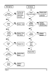
Fail to light up No Volume Check LED indication OK Look up user NG manual ,and follow indica- mal Sensor OK Check Speaker NG Replace Speaker OK OK Check Fan NG Replace Fan OK Check Main Board NG Replace Main Board Check Main Board OK Replace Main OK Check Ballast NG Replace Ballast Chapter 4 32 tive action Check Lamp NG Replace Lamp Check Top cover's cable NG Replace cable or connect the cable back OK Check Speaker Connector NG Speaker Connector Become loose OK Check Thermal Sensor NG Replace Ther-
Fail to light up No Volume Check LED indication OK Look up user NG manual ,and follow indica- mal Sensor OK Check Speaker NG Replace Speaker OK OK Check Fan NG Replace Fan OK Check Main Board NG Replace Main Board Check Main Board OK Replace Main OK Check Ballast NG Replace Ballast Chapter 4 32 tive action Check Lamp NG Replace Lamp Check Top cover's cable NG Replace cable or connect the cable back OK Check Speaker Connector NG Speaker Connector Become loose OK Check Thermal Sensor NG Replace Ther-

Service Guide
Page 38
Color Missing On Screen OK C/W Cable Connector NG Check Cable Connector OK Check Cable NG Replace Cable OK Check Main Board NG Change Main Board OK Change Optical Engine 33 Chapter 4
Color Missing On Screen OK C/W Cable Connector NG Check Cable Connector OK Check Cable NG Replace Cable OK Check Main Board NG Change Main Board OK Change Optical Engine 33 Chapter 4

Service Guide
Page 39
Operation Function: Remote Control Failure Button Failure Check Battery Level OK Check Remote Control OK Check IR OK Main Board Fail NG Replace Battery NG Replace Remote Control NG Replace IR Check Top cover's cable NG Replace cable or connect the cable back OK Check Button OK NG Replace Button Check Keypad NG Replace Keypad OK Replace Main Board Chapter 4 34
Operation Function: Remote Control Failure Button Failure Check Battery Level OK Check Remote Control OK Check IR OK Main Board Fail NG Replace Battery NG Replace Remote Control NG Replace IR Check Top cover's cable NG Replace cable or connect the cable back OK Check Button OK NG Replace Button Check Keypad NG Replace Keypad OK Replace Main Board Chapter 4 34

Service Guide
Page 40
Power Source: No Power Source After Turning On Fan failure After Turning On Check Lamp Cover Switch OK Check Power Cord OK Check Top Cover (key cable..) NG Replace Lamp Cover or Reassembly NG Replace Power Cord NG Replace cable or key Check Fan Connector OK Check Inner Wires OK Check Fan NG Fan Connector Become loose NG Replace Inner Wires NG Replace Fan OK Check Main Board OK Check Power Board NG Replace Main Board OK Check Main Board OK NG Replace Main Board NG Replace Power Board Replace Power Baord OK Replace Standby Signal cable NG 35 Chapter 4
Power Source: No Power Source After Turning On Fan failure After Turning On Check Lamp Cover Switch OK Check Power Cord OK Check Top Cover (key cable..) NG Replace Lamp Cover or Reassembly NG Replace Power Cord NG Replace cable or key Check Fan Connector OK Check Inner Wires OK Check Fan NG Fan Connector Become loose NG Replace Inner Wires NG Replace Fan OK Check Main Board OK Check Power Board NG Replace Main Board OK Check Main Board OK NG Replace Main Board NG Replace Power Board Replace Power Baord OK Replace Standby Signal cable NG 35 Chapter 4
Service Guide
Page 43
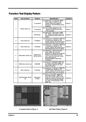
.... Use the projector to adjust the projected image to the maximum size and minimum size and make sure each word is any noises during the stage of turning on the projector, check if the lines and colors of the file. Function Test Display Pattern Item Test Content 1 Noise check up 2 Dust check up 3 Dust check up 4 Resolution check up 5 RGB color check up 6 Dust check up 7 Light leakage check up the projector. Figure...
.... Use the projector to adjust the projected image to the maximum size and minimum size and make sure each word is any noises during the stage of turning on the projector, check if the lines and colors of the file. Function Test Display Pattern Item Test Content 1 Noise check up 2 Dust check up 3 Dust check up 4 Resolution check up 5 RGB color check up 6 Dust check up 7 Light leakage check up the projector. Figure...

Service Guide
Page 45
They will be useful for your detecting the defective boards. Main Board Summarize Connector CN1 CN2 CN3 CN4 CN5 CN6 CN7 J1 J2 J3 J5 J7 J8 J9 J15 JP1 JP3 JP4 JP5 CON1 CON2 CON3 IR Keypad control Fan Fan Fan Fan IR Ballast control Thermal Vidio & S-Video in DMD connector Phone jack stereo-R Color wheel Power in Vidio & S-Video in USB CW index Firmware debug Standby run D-SUB Video S-video Description Chapter 5 40 Connector Information Chapter 5 Introduction This section provides each connector location on boards, signal and function of each board.
They will be useful for your detecting the defective boards. Main Board Summarize Connector CN1 CN2 CN3 CN4 CN5 CN6 CN7 J1 J2 J3 J5 J7 J8 J9 J15 JP1 JP3 JP4 JP5 CON1 CON2 CON3 IR Keypad control Fan Fan Fan Fan IR Ballast control Thermal Vidio & S-Video in DMD connector Phone jack stereo-R Color wheel Power in Vidio & S-Video in USB CW index Firmware debug Standby run D-SUB Video S-video Description Chapter 5 40 Connector Information Chapter 5 Introduction This section provides each connector location on boards, signal and function of each board.
Service Guide
Page 55
Refer to this printed Service Guide. For Acer AUTHORIZED SERVICE PROVIDERS, Acer office may have a DIFFERENT part number code from those given in global configuration of customer machines. Please note that WHEN ORDERING FRU PARTS, you should check the most up-to-date information available on the printed Service Guide. You MUST use the local FRU list provided by your regional Acer office on how...
Refer to this printed Service Guide. For Acer AUTHORIZED SERVICE PROVIDERS, Acer office may have a DIFFERENT part number code from those given in global configuration of customer machines. Please note that WHEN ORDERING FRU PARTS, you should check the most up-to-date information available on the printed Service Guide. You MUST use the local FRU list provided by your regional Acer office on how...


