Quick Start Guide
Page 1
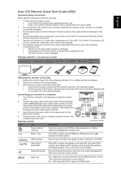
...1 Remove the monitor base from the packaging and place it . 3 Do not apply pressure to view the OSD. White indicates power on the signal cable connector. 3 Insert the monitor power cable into a nearby electrical outlet. Press again to enter a selection in a room with a temperature ...6 Immediately unplug your display. OSD functions Press to the LCD screen. English Acer LCD Monitor Quick Start Guide (QSG) Important safety instructions Please read the following circumstances occur: • Monitor-to-PC signal cable is frayed or damaged. • Liquid spills onto the LCD monitor or...
...1 Remove the monitor base from the packaging and place it . 3 Do not apply pressure to view the OSD. White indicates power on the signal cable connector. 3 Insert the monitor power cable into a nearby electrical outlet. Press again to enter a selection in a room with a temperature ...6 Immediately unplug your display. OSD functions Press to the LCD screen. English Acer LCD Monitor Quick Start Guide (QSG) Important safety instructions Please read the following circumstances occur: • Monitor-to-PC signal cable is frayed or damaged. • Liquid spills onto the LCD monitor or...
User Manual
Page 11
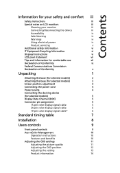
... device (for selected models) 5 Display Data Channel (DDC) 5 Connector pin assignment 5 15-pin color display signal cable 5 24-pin color display signal cable 6 19-pin color display signal cable* 6 Standard timing table 7 Installation 8 Users controls 9 Front panel controls 9 Acer eColor Management 10 Operation instructions 10 Features and benefits 10 Adjusting the OSD settings 11...
... device (for selected models) 5 Display Data Channel (DDC) 5 Connector pin assignment 5 15-pin color display signal cable 5 24-pin color display signal cable 6 19-pin color display signal cable* 6 Standard timing table 7 Installation 8 Users controls 9 Front panel controls 9 Acer eColor Management 10 Operation instructions 10 Features and benefits 10 Adjusting the OSD settings 11...
User Manual
Page 15
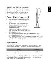
...-colored power LED. Mode On Power saving LED light White Amber The power saving mode will be switched to "power saving" mode by the control signal from "power saving" mode back to the AC inlet, and plug the other end into an AC outlet. • For units using 120 V AC: Use..., type SVT wire and plug rated 10 A/125 V. • For units using both of the monitor. Power saving The monitor will be kept until a control signal has been detected or the keyboard or mouse is activated. The monitor can adjust the monitor tilt, using 220/240 V AC: Use a cord set should...
...-colored power LED. Mode On Power saving LED light White Amber The power saving mode will be switched to "power saving" mode by the control signal from "power saving" mode back to the AC inlet, and plug the other end into an AC outlet. • For units using 120 V AC: Use..., type SVT wire and plug rated 10 A/125 V. • For units using both of the monitor. Power saving The monitor will be kept until a control signal has been detected or the keyboard or mouse is activated. The monitor can adjust the monitor tilt, using 220/240 V AC: Use a cord set should...
User Manual
Page 16
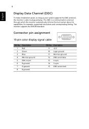
... which the monitor automatically informs the host system about its capabilities; for example, supported resolutions and corresponding timing. Connector pin assignment 15-pin color display signal cable 1 5 6 10 11 15 PIN No. Description 1 Red 2 Green 3 Blue 4 Monitor ground 5 DDC-return 6 R-ground 7 G-ground 8 B-ground PIN No. The monitor supports the DDC2B standard...
... which the monitor automatically informs the host system about its capabilities; for example, supported resolutions and corresponding timing. Connector pin assignment 15-pin color display signal cable 1 5 6 10 11 15 PIN No. Description 1 Red 2 Green 3 Blue 4 Monitor ground 5 DDC-return 6 R-ground 7 G-ground 8 B-ground PIN No. The monitor supports the DDC2B standard...
User Manual
Page 17
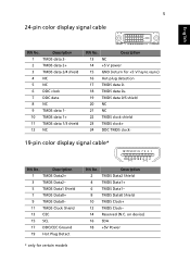
...NC 6 DDC clock 7 DDC data 8 NC 9 TMDS data 1- 10 TMDS data 1+ 11 TMDS data 1/3 shield 12 NC PIN No. 5 24-pin color display signal cable English PIN No. Description 13 NC 14 +5 V power 15 GND (return for certain models on device) 16 SDA 18 +5V Power * only for +5 V ... TMDS data 0+ 19 TMDS data 0/5 shield 20 NC 21 NC 22 TMDS clock shield 23 TMDS clock+ 24 DDC TMDS clock- 19-pin color display signal cable* 1917151311 9 7 5 3 1 1816141210 8 6 4 2 PIN No. Description 2 TMDS Data2 Shield 4 TMDS Data1+ 6 TMDS Data1- 8 TMDS Data0 Shield 10 TMDS Clock+ 12 TMDS...
...NC 6 DDC clock 7 DDC data 8 NC 9 TMDS data 1- 10 TMDS data 1+ 11 TMDS data 1/3 shield 12 NC PIN No. 5 24-pin color display signal cable English PIN No. Description 13 NC 14 +5 V power 15 GND (return for certain models on device) 16 SDA 18 +5V Power * only for +5 V ... TMDS data 0+ 19 TMDS data 0/5 shield 20 NC 21 NC 22 TMDS clock shield 23 TMDS clock+ 24 DDC TMDS clock- 19-pin color display signal cable* 1917151311 9 7 5 3 1 1816141210 8 6 4 2 PIN No. Description 2 TMDS Data2 Shield 4 TMDS Data1+ 6 TMDS Data1- 8 TMDS Data0 Shield 10 TMDS Clock+ 12 TMDS...
User Manual
Page 26
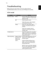
...missing image, please select another resolution or vertical refresh rate. Using the OSD, adjust focus, clock, Hposition and V-position with nonstandard signals. Wait for servicing, please check the troubleshooting list below to their default settings. 14 English Troubleshooting Before sending your system. Check ... mode. Check the display setting on and in compliance which may be causing the input signal frequency mismatch. In case of the image before changing or disconnecting the signal cable or switching off -center, too large or too small on the screen. Image ...
...missing image, please select another resolution or vertical refresh rate. Using the OSD, adjust focus, clock, Hposition and V-position with nonstandard signals. Wait for servicing, please check the troubleshooting list below to their default settings. 14 English Troubleshooting Before sending your system. Check ... mode. Check the display setting on and in compliance which may be causing the input signal frequency mismatch. In case of the image before changing or disconnecting the signal cable or switching off -center, too large or too small on the screen. Image ...
User Manual
Page 27
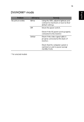
Check the power switch. Check that the computer system is properly connected at the back of monitor. Check if the video signal cable is switched on and in power saving/ standby mode. * for selected models Amber Check if the AC power cord is properly connected to their default settings. 15 English DVI/HDMI* mode Problem No picture visible LED status White Off Remedy Using the OSD, adjust brightness and contrast to maximum or reset to the monitor.
Check the power switch. Check that the computer system is properly connected at the back of monitor. Check if the video signal cable is switched on and in power saving/ standby mode. * for selected models Amber Check if the AC power cord is properly connected to their default settings. 15 English DVI/HDMI* mode Problem No picture visible LED status White Off Remedy Using the OSD, adjust brightness and contrast to maximum or reset to the monitor.


