
Service Guide
Page 6
... Main 34 Advanced 36 Security 37 Boot 41 Exit 42 BIOS Flash Utility 43 Chapter 3 Machine Disassembly and Replacement 45 General Information 46 Before You Begin 46 Disassembly Procedure Flowchart 47 Removing the Battery Pack 50 Removing the Optical Module/HDD Module/Wireless Lan Card and LCD module . .51 Removing the Optical...
... Main 34 Advanced 36 Security 37 Boot 41 Exit 42 BIOS Flash Utility 43 Chapter 3 Machine Disassembly and Replacement 45 General Information 46 Before You Begin 46 Disassembly Procedure Flowchart 47 Removing the Battery Pack 50 Removing the Optical Module/HDD Module/Wireless Lan Card and LCD module . .51 Removing the Optical...
Service Guide
Page 71
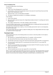
... are correct. 3. If the FFC on Track Pad PCB. In Power Meter, confirm that has less than 7.5 Vdc after recharging, replace the battery. Replace touch pad PCB. 7. Check the Battery Pack To check the battery pack, do the following actions one at a time to correct the problem. For example, run Tracking Pad PS2 Mode Driver...
... are correct. 3. If the FFC on Track Pad PCB. In Power Meter, confirm that has less than 7.5 Vdc after recharging, replace the battery. Replace touch pad PCB. 7. Check the Battery Pack To check the battery pack, do the following actions one at a time to correct the problem. For example, run Tracking Pad PS2 Mode Driver...
Service Guide
Page 84
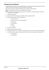
... or whether the system is operating correctly. (See "Power System Check" on the computer. 5. Power-off the computer. 2. Do not replace a non-defective FRU: T System board T LCD assembly Chapter 4 77 justmanuals.com NOTE: Verify that all of the failure is inoperative. ... which installed devices are found, replace the FRU. 3. Determine if the problem has changed. 6. NOTE: Verify that the power supply being used at a time. If the problem remains, replace the following devices: T Non-Acer devices T Printer, mouse, and other external devices T Battery pack T Hard disk drive T...
... or whether the system is operating correctly. (See "Power System Check" on the computer. 5. Power-off the computer. 2. Do not replace a non-defective FRU: T System board T LCD assembly Chapter 4 77 justmanuals.com NOTE: Verify that all of the failure is inoperative. ... which installed devices are found, replace the FRU. 3. Determine if the problem has changed. 6. NOTE: Verify that the power supply being used at a time. If the problem remains, replace the following devices: T Non-Acer devices T Printer, mouse, and other external devices T Battery pack T Hard disk drive T...

Service Guide
Page 110
...voltage 22 package 22 type 22 D DIMM Index Combinations 23 external 51 package 22 removing 51 socket number 22 Speed 22 voltage 22 Disassembly Battery Pack 48 CD-ROM/DVD-ROM Module 53 Floppy Disk Drive 57 Procedure Flowchart 47 Display Standby Mode 29 E Embedded Numeric Keypad 14 ...External CD-ROM Drive Check 62 External Diskette Drive Check 62 F Features on System Specifications 1 Flash Utility 43 Floppy Disk removing the 57 FRU (Field Replaceable Unit) List 87 Exploded Diagram 88 H Hard Disk Standby Mode 29 Hibernation Mode 29 Hot Keys 13, 16 I Indicators 12 Intermittent Problems 76 J...
...voltage 22 package 22 type 22 D DIMM Index Combinations 23 external 51 package 22 removing 51 socket number 22 Speed 22 voltage 22 Disassembly Battery Pack 48 CD-ROM/DVD-ROM Module 53 Floppy Disk Drive 57 Procedure Flowchart 47 Display Standby Mode 29 E Embedded Numeric Keypad 14 ...External CD-ROM Drive Check 62 External Diskette Drive Check 62 F Features on System Specifications 1 Flash Utility 43 Floppy Disk removing the 57 FRU (Field Replaceable Unit) List 87 Exploded Diagram 88 H Hard Disk Standby Mode 29 Hibernation Mode 29 Hot Keys 13, 16 I Indicators 12 Intermittent Problems 76 J...


