
Service Guide
Page 6
... Service Guide. You MUST use the list provided by your regional web or channel. add-on your regional Acer office to the BASIC CONFIGURATION decided for Acer's "global" product offering. Service Guide Coverage This Service Guide provides you with further technical details. In such... cases, please contact your regional office MAY have a DIFFERENT part number code to -date information available on card, modem, or extra memory capability). vi...
... Service Guide. You MUST use the list provided by your regional web or channel. add-on your regional Acer office to the BASIC CONFIGURATION decided for Acer's "global" product offering. Service Guide Coverage This Service Guide provides you with further technical details. In such... cases, please contact your regional office MAY have a DIFFERENT part number code to -date information available on card, modem, or extra memory capability). vi...
Service Guide
Page 7
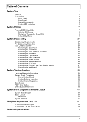
... Fan Assembly 32 Removing the Processor 34 Removing the Optical Drive 36 Removing the Hard Disk Drive 38 Removing the Power Supply 41 Removing the Memory Modules 44 Removing the PCI Card 45 Removing the Front I/O and Card Reader Boards 47 Removing the Mainboard 51 System Troubleshooting 53 Hardware Diagnostic Procedure...System Block Diagram and Board Layout 63 System Block Diagram 63 Board Layout 64 Mainboard 64 System Jumpers 65 FRU (Field Replaceable Unit) List 67 EL1210 Exploded Diagram 68 EL1210 FRU List (81.3V801.007G) 69 Technical Specifications 73 vii
... Fan Assembly 32 Removing the Processor 34 Removing the Optical Drive 36 Removing the Hard Disk Drive 38 Removing the Power Supply 41 Removing the Memory Modules 44 Removing the PCI Card 45 Removing the Front I/O and Card Reader Boards 47 Removing the Mainboard 51 System Troubleshooting 53 Hardware Diagnostic Procedure...System Block Diagram and Board Layout 63 System Block Diagram 63 Board Layout 64 Mainboard 64 System Jumpers 65 FRU (Field Replaceable Unit) List 67 EL1210 Exploded Diagram 68 EL1210 FRU List (81.3V801.007G) 69 Technical Specifications 73 vii
Service Guide
Page 9
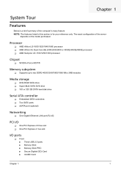
...667/800/1066 MHz UNB modules Media storage DVD-ROM SATA drive Super-Multi SATA DVD drive 160 or 320 GB SATA hard disk drive Serial ATA controller Embedded SATA controllers Two SATA ports eSATA port (optional) Networking ...61553; One PCI Express x16 bus slot One PCI Express x1 bus slot I/O ports Front Three USB 2.0 ports Memory Stick Memory Stick PRO Secure Digitial (SD) Card miniSD Card Chapter 1 1 The exact configuration of the computer's many feature: NOTE: The ...
...667/800/1066 MHz UNB modules Media storage DVD-ROM SATA drive Super-Multi SATA DVD drive 160 or 320 GB SATA hard disk drive Serial ATA controller Embedded SATA controllers Two SATA ports eSATA port (optional) Networking ...61553; One PCI Express x16 bus slot One PCI Express x1 bus slot I/O ports Front Three USB 2.0 ports Memory Stick Memory Stick PRO Secure Digitial (SD) Card miniSD Card Chapter 1 1 The exact configuration of the computer's many feature: NOTE: The ...
Service Guide
Page 15
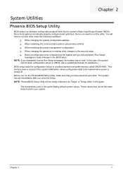
... the configuration values in CMOS. These values may be simply referred to as "Setup" or "Setup utility" in this utility. This memory area is turned off. Before you repeatedly receive Run Setup messages, the battery may not be retained when power is not part of the...allows configuration data to be the same those found in this case, the system cannot retain configuration values in a battery-backed nonvolatile memory called CMOS RAM. Since most systems are prompted ("Run Setup" message) to make sure that you close the Setup. NOTE: PhoenixBIOS Setup Utility will...
... the configuration values in CMOS. These values may be simply referred to as "Setup" or "Setup utility" in this utility. This memory area is turned off. Before you repeatedly receive Run Setup messages, the battery may not be retained when power is not part of the...allows configuration data to be the same those found in this case, the system cannot retain configuration values in a battery-backed nonvolatile memory called CMOS RAM. Since most systems are prompted ("Run Setup" message) to make sure that you close the Setup. NOTE: PhoenixBIOS Setup Utility will...
Service Guide
Page 19
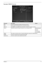
... Halt On DIMM1 DIMM2 Total Memory Description Option Set the date following the hour-minute-second format. Set the system time following the weekday-month-day-year format. Typically, 640 KB will stop for the MS-DOS OS. Total size of extended memory detected during POST Total size ...of system memory detected during the POST. Press Enter to view detailed device information connected to the SATA connectors. Determines whether the system...
... Halt On DIMM1 DIMM2 Total Memory Description Option Set the date following the hour-minute-second format. Set the system time following the weekday-month-day-year format. Typically, 640 KB will stop for the MS-DOS OS. Total size of extended memory detected during POST Total size ...of system memory detected during the POST. Press Enter to view detailed device information connected to the SATA connectors. Determines whether the system...
Service Guide
Page 24
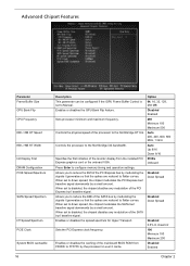
... Express graphics card or the onboard VGA. When set to FFFFFh by modulating the signals it generates so that the spikes are reduced to configure memory timing and operation settings. Press Enter to flatter curves. Allows you to reduce the EMI of the monitor display from F0000h to disabled, the chipset...
... Express graphics card or the onboard VGA. When set to FFFFFh by modulating the signals it generates so that the spikes are reduced to configure memory timing and operation settings. Press Enter to flatter curves. Allows you to reduce the EMI of the monitor display from F0000h to disabled, the chipset...

Service Guide
Page 25
...through disasserting clock enable using system level or per channel basis. DRAM Configuration Parameter Timing Mode Memory Clock value or Limit CKE base power down mode CKE based power down Memclock tri-stating Memory Hole Remapping Auto Optimize Bottom IO Bottom of UMA DRAM [31:24] [FC] Description ...off, the device will lose all data, however, as long as the clock enable (CKE) signal is disasserted. Enables or disables memory remapping around the memory hole. Allows you can go into auto-refresh mode which is maintained, no data loss will occur. When set to auto optimize ...
...through disasserting clock enable using system level or per channel basis. DRAM Configuration Parameter Timing Mode Memory Clock value or Limit CKE base power down mode CKE based power down Memclock tri-stating Memory Hole Remapping Auto Optimize Bottom IO Bottom of UMA DRAM [31:24] [FC] Description ...off, the device will lose all data, however, as long as the clock enable (CKE) signal is disasserted. Enables or disables memory remapping around the memory hole. Allows you can go into auto-refresh mode which is maintained, no data loss will occur. When set to auto optimize ...

Service Guide
Page 30
Setup defaults are using low-speed memory chips or other kinds of resources consumption. Load Default Settings The Load Default Settings menu allows you to load these settings, the system might not function properly. 22 Chapter 2 If you are quite demanding in terms of low-performance components and you choose to load the default settings for all BIOS setup parameters.
Setup defaults are using low-speed memory chips or other kinds of resources consumption. Load Default Settings The Load Default Settings menu allows you to load these settings, the system might not function properly. 22 Chapter 2 If you are quite demanding in terms of low-performance components and you choose to load the default settings for all BIOS setup parameters.
Service Guide
Page 37
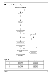
Main Unit Disassembly MAIN UNIT DISASSEMBLY MAIN UNIT Ax2 SIDE PANEL FRONT BEZEL HEAT SINK FAN ASSEMBLY CPU Bx1 OPTICAL DISK DRIVE Cx1 HDD-ODD BRACKET Ax3 Cx1 POWER SUPPLY Dx4 HDD MODULE HDD MEMORY MODULES Ex1 PCI CARD Dx2 FRONT I/O AND CARD READER BOARD BRACKET Cx6 MAINBOARD Cx2 FRONT I/O BOARD Cx2 CARD READER BOARD Screw List A B C D E Chapter 3 Screw #6-32 L5 BZN M3xL5 BZN #6-32 L6 NI #6-32*3/16 NI #6-32 5MM NI Part No. 86.00J07.B60 86.1A324.5R0 86.00J44.C60 86.5A5B6.012 86.9A5G6.162 29
Main Unit Disassembly MAIN UNIT DISASSEMBLY MAIN UNIT Ax2 SIDE PANEL FRONT BEZEL HEAT SINK FAN ASSEMBLY CPU Bx1 OPTICAL DISK DRIVE Cx1 HDD-ODD BRACKET Ax3 Cx1 POWER SUPPLY Dx4 HDD MODULE HDD MEMORY MODULES Ex1 PCI CARD Dx2 FRONT I/O AND CARD READER BOARD BRACKET Cx6 MAINBOARD Cx2 FRONT I/O BOARD Cx2 CARD READER BOARD Screw List A B C D E Chapter 3 Screw #6-32 L5 BZN M3xL5 BZN #6-32 L6 NI #6-32*3/16 NI #6-32 5MM NI Part No. 86.00J07.B60 86.1A324.5R0 86.00J44.C60 86.5A5B6.012 86.9A5G6.162 29

Service Guide
Page 52
... 36. 6. Gently pull the DIMM upward to create a backup file of the DIMM slot outward to release the DIMM. 8. Removing the Memory Modules IMPORTANT:Before removing any DIMM from the memory board, make sure to pull it away from the chassis. 44 Chapter 3 See "Removing the Optical Drive" on page 31. 3. See...
... 36. 6. Gently pull the DIMM upward to create a backup file of the DIMM slot outward to release the DIMM. 8. Removing the Memory Modules IMPORTANT:Before removing any DIMM from the memory board, make sure to pull it away from the chassis. 44 Chapter 3 See "Removing the Optical Drive" on page 31. 3. See...
Service Guide
Page 55
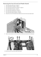
See "Removing the Processor" on page 44. 8. Disconnect one end of the USB and audio cables from the mainboard. 10. See "Removing the Memory Modules" on page 34. 5. Chapter 3 47 See "Removing the Front Bezel" on page 38. 7. Open the cable retention clip, then disconnect the USB and audio ...
See "Removing the Processor" on page 44. 8. Disconnect one end of the USB and audio cables from the mainboard. 10. See "Removing the Memory Modules" on page 34. 5. Chapter 3 47 See "Removing the Front Bezel" on page 38. 7. Open the cable retention clip, then disconnect the USB and audio ...

Service Guide
Page 59
See "Removing the Processor" on page 31. 3. Disconnect the LED cable from the mainboard. See "Removing the Front Bezel" on page 34. 5. See "Removing the Hard Disk Drive" on page 47. 10. See "Removing the Front I/O and Card Reader Boards" on page 38. 7. See "Removing the Memory Modules" on page 32. 4. See "Removing the Heat Sink Fan Assembly" on page 44. 8. See "Removing the Optical Drive" on page 45. 9. Chapter 3 51 Removing the Mainboard 1. See "Removing the PCI Card" on page 36. 6. See "Removing the Side Panel" on page 30. 2.
See "Removing the Processor" on page 31. 3. Disconnect the LED cable from the mainboard. See "Removing the Front Bezel" on page 34. 5. See "Removing the Hard Disk Drive" on page 47. 10. See "Removing the Front I/O and Card Reader Boards" on page 38. 7. See "Removing the Memory Modules" on page 32. 4. See "Removing the Heat Sink Fan Assembly" on page 44. 8. See "Removing the Optical Drive" on page 45. 9. Chapter 3 51 Removing the Mainboard 1. See "Removing the PCI Card" on page 36. 6. See "Removing the Side Panel" on page 30. 2.

Service Guide
Page 63
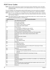
... right corner of the screen during POST. Not all computers using AMIBIOS enable this feature. System is the best tool for viewing AMIBIOS checkpoints. Memory not installed or memory error. Beep codes are used when an error occurs before the system video has been initialized. VGA not installed or VGA error. Beep...
... right corner of the screen during POST. Not all computers using AMIBIOS enable this feature. System is the best tool for viewing AMIBIOS checkpoints. Memory not installed or memory error. Beep codes are used when an error occurs before the system video has been initialized. VGA not installed or VGA error. Beep...
Service Guide
Page 64
...06h 07h 08h 09h 0Ah 0Bh 0Ch 0Dh 0Eh 0Fh 10h 11h POST Routine Description Test CMOS R/W functionality Early chipset initialization Disable shadow RAM Disable L2 cache (socket 7 or below ) Expand compressed BIOS code to DRAM Call chipset hook to copy BIOS back to E000 and...see whether it has been configured. If the symptom is rewritable or not. Some of them display information about a hardware device, e.g., the amount of memory installed. NOTE: If the system fails after you make changes in the computer. If test fails, keep beeping the speaker. Do not replace a ...
...06h 07h 08h 09h 0Ah 0Bh 0Ch 0Dh 0Eh 0Fh 10h 11h POST Routine Description Test CMOS R/W functionality Early chipset initialization Disable shadow RAM Disable L2 cache (socket 7 or below ) Expand compressed BIOS code to DRAM Call chipset hook to copy BIOS back to E000 and...see whether it has been configured. If the symptom is rewritable or not. Some of them display information about a hardware device, e.g., the amount of memory installed. NOTE: If the system fails after you make changes in the computer. If test fails, keep beeping the speaker. Do not replace a ...
Service Guide
Page 65
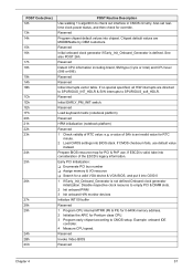
...interrupts are MODBINable by OEM customers. Reserved Reserved Initial interrupts vector table. Early PCI Initialization: Enumerate PCI bus number Assign memory & I/O resource Search for a valid VGA device & VGA BIOS, and put it into C000:0 1 If Early_Init_Onboard_Generator is an ... Init onboard PWM 3 Init onboard H/W monitor devices Initialize INT 09 buffer Reserved 1 Program CPU internal MTRR (P6 & PII) for 0-640K memory address. 2 Initialize the APIC for RTC minute. 2 Load CMOS settings into BIOS stack. Example: onboard IDE controller. 4 Measure CPU speed...
...interrupts are MODBINable by OEM customers. Reserved Reserved Initial interrupts vector table. Early PCI Initialization: Enumerate PCI bus number Assign memory & I/O resource Search for a valid VGA device & VGA BIOS, and put it into C000:0 1 If Early_Init_Onboard_Generator is an ... Init onboard PWM 3 Init onboard H/W monitor devices Initialize INT 09 buffer Reserved 1 Program CPU internal MTRR (P6 & PII) for 0-640K memory address. 2 Initialize the APIC for RTC minute. 2 Load CMOS settings into BIOS stack. Example: onboard IDE controller. 4 Measure CPU speed...

Service Guide
Page 66
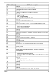
... cacheable ranges between each 64K page. 2 Program write allocation for channel 2 Reserved Reserved Test 8259 functionality Reserved Reserved Reserved Initialize EISA slot Reserved 1 Calculate total memory by testing the last double word of each CPU are not identical Reserved Initialize the USB Keyboard & Mouse 58 Chapter 4 Reserved Reserved Reserved Reserved Reserved...
... cacheable ranges between each 64K page. 2 Program write allocation for channel 2 Reserved Reserved Test 8259 functionality Reserved Reserved Reserved Initialize EISA slot Reserved 1 Calculate total memory by testing the last double word of each CPU are not identical Reserved Initialize the USB Keyboard & Mouse 58 Chapter 4 Reserved Reserved Reserved Reserved Reserved...
Service Guide
Page 67
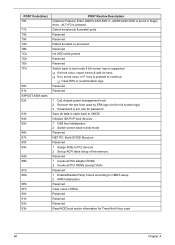
... ports to onboard COM ports if the corresponding item in 40:hardware Reserved Reserved Reserved Reserved Reserved Detect & install all extended memory to 0) Clear password according to H/W jumper (Optional) Reserved Display number of processors (multi-processor platform) Reserved 1 Display ...1 Initialize floppy controller 2 Set up floppy related fields in Setup is not defined Reserved Initialize PS/2 Mouse Reserved Prepare memory size information for entering AWDFLASH.EXE from FDD Reserved 1 Initialize Init_Onboard_Super_IO 2 Initialize Init_Onbaord_AUDIO Reserved Reserved Okay to "AUTO"....
... ports to onboard COM ports if the corresponding item in 40:hardware Reserved Reserved Reserved Reserved Reserved Detect & install all extended memory to 0) Clear password according to H/W jumper (Optional) Reserved Display number of processors (multi-processor platform) Reserved 1 Display ...1 Initialize floppy controller 2 Set up floppy related fields in Setup is not defined Reserved Initialize PS/2 Mouse Reserved Prepare memory size information for entering AWDFLASH.EXE from FDD Reserved 1 Initialize Init_Onboard_Super_IO 2 Initialize Init_Onbaord_AUDIO Reserved Reserved Okay to "AUTO"....
Service Guide
Page 68
..., report errors & wait for keys If no errors occur or F1 key is pressed to CMOS setup 2 APM Initialization Reserved Clear noise of the memory Reserved 1 Invoke all ISA adapter ROMs 2 Invoke all PCI ROMs (except VGA) Reserved 1 Enable/Disable Parity Check according to continue: Clear EPA or customization...
..., report errors & wait for keys If no errors occur or F1 key is pressed to CMOS setup 2 APM Initialization Reserved Clear noise of the memory Reserved 1 Invoke all ISA adapter ROMs 2 Invoke all PCI ROMs (except VGA) Reserved 1 Enable/Disable Parity Check according to continue: Clear EPA or customization...
Service Guide
Page 72
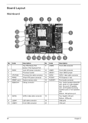
... connector 12 USBF1 3 Processor socket 13 JBIOS1 4 CPUFAN1 Processor fan cable connector 14 SATA1 5 PWR2 24-pin ATX power connector 15 PCIEX1 6 DIMM1 and 2 System memory slots 16 AUDIOF1 7 DEBUGH1 Debug connector 17 8 SATA2 9 LEDH1 10 USBF3 SATA 2 data cable connector 18 LED cable connector 19 Front USB connector 20 Description...
... connector 12 USBF1 3 Processor socket 13 JBIOS1 4 CPUFAN1 Processor fan cable connector 14 SATA1 5 PWR2 24-pin ATX power connector 15 PCIEX1 6 DIMM1 and 2 System memory slots 16 AUDIOF1 7 DEBUGH1 Debug connector 17 8 SATA2 9 LEDH1 10 USBF3 SATA 2 data cable connector 18 LED cable connector 19 Front USB connector 20 Description...


