
Service Guide
Page 6
... or the responsible personnel/channel to provide you with all technical information relating to those given in this printed Service Guide. If, for Acer's "global" product offering. FRU Information Please note WHEN ORDERING FRU PARTS, that you should check the most up-to-date information available... on card, modem, or extra memory capability). In such cases, please contact your regional web or channel. vi Service Guide Coverage This Service Guide provides you with further technical ...
... or the responsible personnel/channel to provide you with all technical information relating to those given in this printed Service Guide. If, for Acer's "global" product offering. FRU Information Please note WHEN ORDERING FRU PARTS, that you should check the most up-to-date information available... on card, modem, or extra memory capability). In such cases, please contact your regional web or channel. vi Service Guide Coverage This Service Guide provides you with further technical ...

Service Guide
Page 7
...Fan Assembly 32 Removing the Processor 34 Removing the Optical Drive 36 Removing the Hard Disk Drive 39 Removing the Power Supply 40 Removing the Memory Modules 42 Removing an Expansion Card 43 Removing the Front I/O and Card Reader Boards 46 Removing the Mainboard 49 Removing the Top Bezel 51... Code Checkpoints 55 Bootblock Recovery Code Checkpoints 56 POST Code Checkpoints 57 DIM Code Checkpoints 59 ACPI Runtime Checkpoints 59 Error Messages 60 Memory 60 Boot 60 Storage Device 61 Virus Related 62 System Configuration 63 CMOS 64 Miscellaneous 64 vii
...Fan Assembly 32 Removing the Processor 34 Removing the Optical Drive 36 Removing the Hard Disk Drive 39 Removing the Power Supply 40 Removing the Memory Modules 42 Removing an Expansion Card 43 Removing the Front I/O and Card Reader Boards 46 Removing the Mainboard 49 Removing the Top Bezel 51... Code Checkpoints 55 Bootblock Recovery Code Checkpoints 56 POST Code Checkpoints 57 DIM Code Checkpoints 59 ACPI Runtime Checkpoints 59 Error Messages 60 Memory 60 Boot 60 Storage Device 61 Virus Related 62 System Configuration 63 CMOS 64 Miscellaneous 64 vii
Service Guide
Page 9
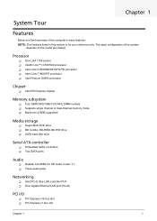
...; Intel Core i7-860/870 processor Intel Pentium G6950 processor Chipset Intel P55 Express chipset Memory subsystem Four DDR3-800/1066/1333 MHz DIMM sockets Supports single channel or dual-channel memory mode Maximum of the computer's many features: NOTE: The features listed in this section is...
...; Intel Core i7-860/870 processor Intel Pentium G6950 processor Chipset Intel P55 Express chipset Memory subsystem Four DDR3-800/1066/1333 MHz DIMM sockets Supports single channel or dual-channel memory mode Maximum of the computer's many features: NOTE: The features listed in this section is...
Service Guide
Page 10
... Reduced-Size MultiMediaCard (RS-MMC), Secure Digital™ (SD) Card, xD-Picture Card™, Memory Stick™, Memory Stick PRO™ Rear PS/2 keyboard port PS/2 mouse port... Windows 7 Home Basic X86, FreeDOS Linux LL95 Applications Acer eRecovery Management Acrobat Reader Acrobat Flash Player Arcade Deluxe Cyberlink Power...power supply Dimension and weight Dimension (DxWxH) X3950: 367.8 x 100 x 281.5 mm (with bezel) X5950: 367.8 x 100 x 281.5 mm...
... Reduced-Size MultiMediaCard (RS-MMC), Secure Digital™ (SD) Card, xD-Picture Card™, Memory Stick™, Memory Stick PRO™ Rear PS/2 keyboard port PS/2 mouse port... Windows 7 Home Basic X86, FreeDOS Linux LL95 Applications Acer eRecovery Management Acrobat Reader Acrobat Flash Player Arcade Deluxe Cyberlink Power...power supply Dimension and weight Dimension (DxWxH) X3950: 367.8 x 100 x 281.5 mm (with bezel) X5950: 367.8 x 100 x 281.5 mm...

Service Guide
Page 14
Component 1 Optical drive 2 Memory 3 Expansion cards 4 Mainboard 5 Heatsink fan assembly 6 Power supply 6 Chapter 1 Internal Components No.
Component 1 Optical drive 2 Memory 3 Expansion cards 4 Mainboard 5 Heatsink fan assembly 6 Power supply 6 Chapter 1 Internal Components No.
Service Guide
Page 17
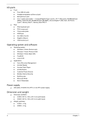
... Setup" message) to make sure that you have saved all open files. The screenshots used in this guide. Chapter 2 9 This memory area is not part of the system RAM which allows configuration data to be retained when power is detected by the system and you ... may be bad. CMOS setup loads the configuration values in your system. You will be the same those found in a battery-backed nonvolatile memory called the complementary metaloxide semiconductor (CMOS) Setup Utility. In this utility under the following conditions. When changing the system configuration settings ...
... Setup" message) to make sure that you have saved all open files. The screenshots used in this guide. Chapter 2 9 This memory area is not part of the system RAM which allows configuration data to be retained when power is detected by the system and you ... may be bad. CMOS setup loads the configuration values in your system. You will be the same those found in a battery-backed nonvolatile memory called the complementary metaloxide semiconductor (CMOS) Setup Utility. In this utility under the following conditions. When changing the system configuration settings ...
Service Guide
Page 20
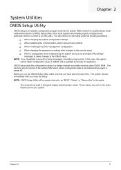
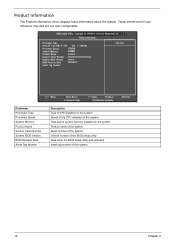
...basic information about the system. Product Information Processor Type Intel (R) Core(TM) i5 CPU 650 @ 3.20GHz Processor Speed 3.20GHz System Memory 2048MB Product Name xxxxxxx System Serial Number xxxxxxxxxxxxxxxxxxxxxx System BIOS Version xxx-xx BIOS Release Date 03/22/2010 Asset Tag Number Help Item... Parameter Processor Type Processor Speed System Memory Product Name System Serial Number System BIOS Version BIOS Release Date Asset Tag Number :Move Enter:Select F1:General Help +/-/:Value...
...basic information about the system. Product Information Processor Type Intel (R) Core(TM) i5 CPU 650 @ 3.20GHz Processor Speed 3.20GHz System Memory 2048MB Product Name xxxxxxx System Serial Number xxxxxxxxxxxxxxxxxxxxxx System BIOS Version xxx-xx BIOS Release Date 03/22/2010 Asset Tag Number Help Item... Parameter Processor Type Processor Speed System Memory Product Name System Serial Number System BIOS Version BIOS Release Date Asset Tag Number :Move Enter:Select F1:General Help +/-/:Value...

Service Guide
Page 23
...code in the buffer preventing damage and worm propagation. Select the amout of overlapped PCI memory above the total physical memory. Enables or disables Intel Turbo Boost Technology. Select a video memory mode. When enabled, the processor disables code execution when a worm attempts to 0....Chipset Features Advanced Chipset Features Help Item Intel EIST Intel Turbo Boost Intel AES-NI Intel XD Bit Intel VT Memory Hole Remapping Primary Video Video Memory Size DVMT Mode DVMT/Fixed Memory Size [Enabled] [Enabled] [Disabled] [Enabled] [Enabled] [Enabled] [Auto] [32MB] [DVMT] [...
...code in the buffer preventing damage and worm propagation. Select the amout of overlapped PCI memory above the total physical memory. Enables or disables Intel Turbo Boost Technology. Select a video memory mode. When enabled, the processor disables code execution when a worm attempts to 0....Chipset Features Advanced Chipset Features Help Item Intel EIST Intel Turbo Boost Intel AES-NI Intel XD Bit Intel VT Memory Hole Remapping Primary Video Video Memory Size DVMT Mode DVMT/Fixed Memory Size [Enabled] [Enabled] [Disabled] [Enabled] [Enabled] [Enabled] [Auto] [32MB] [DVMT] [...
Service Guide
Page 30
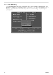
CMOS Setup Utility - ESC:Exit 22 Chapter 2 Setup defaults are using low-speed memory chips or other kinds of resources consumption. Copyright © 1985-2010, American Megatrends, Inc. ► Product Information ► PC Health Status ► Standard CMOS Features &#...
CMOS Setup Utility - ESC:Exit 22 Chapter 2 Setup defaults are using low-speed memory chips or other kinds of resources consumption. Copyright © 1985-2010, American Megatrends, Inc. ► Product Information ► PC Health Status ► Standard CMOS Features &#...
Service Guide
Page 35
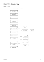
Main Unit Disassembly X3950 model MAIN UNIT DISASSEMBLY MAIN UNIT Ax2 SIDE PANEL FRONT BEZEL HEATSINK FAN ASSEMBLY PROCESSOR Cx2 HDD-ODD BRACKET Ax3, Bx1 POWER SUPPLY MEMORY MODULES PCI CARD Bx1 FRONT I/O AND CARD READER BOARD BRACKET Bx6 MAINBOARD Bx2 OPTICAL DISK DRIVE Dx4 HDD MODULE HDD Ax1 TV TUNER CARD or NETWORK CARD or GRAPHICS CARD Bx2 FRONT I/O BOARD Bx2 CARD READER BOARD Chapter 3 27
Main Unit Disassembly X3950 model MAIN UNIT DISASSEMBLY MAIN UNIT Ax2 SIDE PANEL FRONT BEZEL HEATSINK FAN ASSEMBLY PROCESSOR Cx2 HDD-ODD BRACKET Ax3, Bx1 POWER SUPPLY MEMORY MODULES PCI CARD Bx1 FRONT I/O AND CARD READER BOARD BRACKET Bx6 MAINBOARD Bx2 OPTICAL DISK DRIVE Dx4 HDD MODULE HDD Ax1 TV TUNER CARD or NETWORK CARD or GRAPHICS CARD Bx2 FRONT I/O BOARD Bx2 CARD READER BOARD Chapter 3 27
Service Guide
Page 36
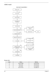
X5950 model MAIN UNIT DISASSEMBLY MAIN UNIT Ax2 SIDE PANEL FRONT BEZEL HEATSINK FAN ASSEMBLY PROCESSOR Cx2 HDD-ODD BRACKET Ax3, Bx1 POWER SUPPLY MEMORY MODULES PCI CARD Bx1 FRONT I/O AND CARD READER BOARD BRACKET Bx6 MAINBOARD TOP BEZEL Bx2 OPTICAL DISK DRIVE Dx4 HDD MODULE HDD Ax1 TV TUNER CARD or NETWORK CARD or GRAPHICS CARD Bx2 FRONT I/O BOARD Bx2 CARD READER BOARD Screw List Code A B C D 28 Screw #6-32 L5 BZN #6-32 L6 NI M3xL5 BZN #6-32*3/16 NI Part No. 86.00J07.B60 86.00J44.C60 86.1A324.5R0 86.5A5B6.012 Chapter 3
X5950 model MAIN UNIT DISASSEMBLY MAIN UNIT Ax2 SIDE PANEL FRONT BEZEL HEATSINK FAN ASSEMBLY PROCESSOR Cx2 HDD-ODD BRACKET Ax3, Bx1 POWER SUPPLY MEMORY MODULES PCI CARD Bx1 FRONT I/O AND CARD READER BOARD BRACKET Bx6 MAINBOARD TOP BEZEL Bx2 OPTICAL DISK DRIVE Dx4 HDD MODULE HDD Ax1 TV TUNER CARD or NETWORK CARD or GRAPHICS CARD Bx2 FRONT I/O BOARD Bx2 CARD READER BOARD Screw List Code A B C D 28 Screw #6-32 L5 BZN #6-32 L6 NI M3xL5 BZN #6-32*3/16 NI Part No. 86.00J07.B60 86.00J44.C60 86.1A324.5R0 86.5A5B6.012 Chapter 3

Service Guide
Page 50
.... 2. NOTE: The DIMM has been highlighted with a yellow rectangle as above image shows. Please detach the DIMM and follow local regulations for disposal. (4). Removing the Memory Modules IMPORTANT:Before removing any DIMM, make sure to remove the other modules. 42 Chapter 3 See "Removing the Front Bezel" on page 36. 4. See "Remove...
.... 2. NOTE: The DIMM has been highlighted with a yellow rectangle as above image shows. Please detach the DIMM and follow local regulations for disposal. (4). Removing the Memory Modules IMPORTANT:Before removing any DIMM, make sure to remove the other modules. 42 Chapter 3 See "Removing the Front Bezel" on page 36. 4. See "Remove...
Service Guide
Page 57
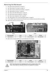
See "Removing the Front Bezel" on page 36. 6. X3950 X5950 Screw (Quantity) M3xL5 BZN (1) Color Black Torque 5.5 to 6.3 kgf-cm Part No. 86.00J44.C60 NOTE: The mainboard has been highlighted with a yellow rectangle ... screw (C) on page 29. 2. See "Removing the Side Panel" on the rear panel. See "Removing the Heatsink Fan Assembly" on page 42. 7. See "Removing the Memory Modules" on page 32. 4. See "Removing an Expansion Card" on page 43. 8. Chapter 3 49 For the X5950 model, disconnect the LED cable from its mainboard...
See "Removing the Front Bezel" on page 36. 6. X3950 X5950 Screw (Quantity) M3xL5 BZN (1) Color Black Torque 5.5 to 6.3 kgf-cm Part No. 86.00J44.C60 NOTE: The mainboard has been highlighted with a yellow rectangle ... screw (C) on page 29. 2. See "Removing the Side Panel" on the rear panel. See "Removing the Heatsink Fan Assembly" on page 42. 7. See "Removing the Memory Modules" on page 32. 4. See "Removing an Expansion Card" on page 43. 8. Chapter 3 49 For the X5950 model, disconnect the LED cable from its mainboard...
Service Guide
Page 63
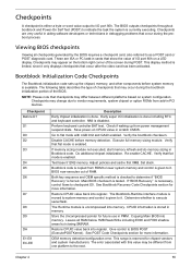
... NMI is tested. Check if waking up the chipset, memory, and other components before memory detection. Execute full memory sizing module. If memory sizing module not executed, start memory refresh and do memory sizing in memory. Re-enable CACHE. Adjust policies and cache first 8MB. ...all checkpoints generated by the BIOS requires a checkpoint card, also referred to indicate the task the system is currently executing. OEM memory detection/configuration error. Go to I/O port 80h. See Bootblock Recovery Code Checkpoints section for more information. Checkpoints A checkpoint is...
... NMI is tested. Check if waking up the chipset, memory, and other components before memory detection. Execute full memory sizing module. If memory sizing module not executed, start memory refresh and do memory sizing in memory. Re-enable CACHE. Adjust policies and cache first 8MB. ...all checkpoints generated by the BIOS requires a checkpoint card, also referred to indicate the task the system is currently executing. OEM memory detection/configuration error. Go to I/O port 80h. See Bootblock Recovery Code Checkpoints section for more information. Checkpoints A checkpoint is...
Service Guide
Page 66
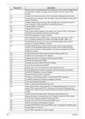
...initialization of chipset registers. Check boot password if installed. Initialize runtime language module. Activate ADM module. Initializes different devices through DIM. Display total memory in system RAM size if needed . Log errors encountered during POST. End of POST initialization of chipset registers. Initializes NUM-LOCK status and ...75 78 7A 7C 84 85 87 8C 8D 8E 90 A0 A1 A2 A4 A7 A8 A9 AA AB AC 58 Description Allocate memory for OS boot including final MTRR values. Initializes the Microsoft IRQ Routing Table. Execute BIOS setup if needed . Prepare CPU for ...
...initialization of chipset registers. Check boot password if installed. Initialize runtime language module. Activate ADM module. Initializes different devices through DIM. Display total memory in system RAM size if needed . Log errors encountered during POST. End of POST initialization of chipset registers. Initializes NUM-LOCK status and ...75 78 7A 7C 84 85 87 8C 8D 8E 90 A0 A1 A2 A4 A7 A8 A9 AA AB AC 58 Description Allocate memory for OS boot including final MTRR values. Initializes the Microsoft IRQ Routing Table. Execute BIOS setup if needed . Prepare CPU for ...
Service Guide
Page 67
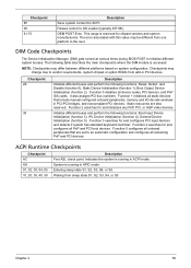
... Disable (function 0); Function 3 searches for and initializes any PnP, PCI, or AGP video devices. Function 5 configures all onboard peripherals that include manual configured onboard peripherals, memory and I/O decode windows in PCI devices. Checkpoint B1 00 61-70 Description Save system context for chipset vendors and system manufacturers. Passes control to initialize...
... Disable (function 0); Function 3 searches for and initializes any PnP, PCI, or AGP video devices. Function 5 configures all onboard peripherals that include manual configured onboard peripherals, memory and I/O decode windows in PCI devices. Checkpoint B1 00 61-70 Description Save system context for chipset vendors and system manufacturers. Passes control to initialize...
Service Guide
Page 68
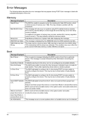
...in selected Boot device BIOS could not find a bootable device in the system and/or removable media drive does not contain media. Fatal Memory Parity Error. The base memory (memory below 1MB) size that is reported in the drive, but was unable to properly configure the device. This message is usually followed ...often reported by drives when no bootable device can be due to boot from a particular device. This message occurs on systems using ECC enabled memory modules. Error Messages The following tables describes the error messages that may occur when the hole is set at 512K base...
...in selected Boot device BIOS could not find a bootable device in the system and/or removable media drive does not contain media. Fatal Memory Parity Error. The base memory (memory below 1MB) size that is reported in the drive, but was unable to properly configure the device. This message is usually followed ...often reported by drives when no bootable device can be due to boot from a particular device. This message occurs on systems using ECC enabled memory modules. Error Messages The following tables describes the error messages that may occur when the hole is set at 512K base...
Service Guide
Page 71
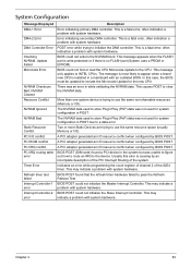
...Update for the new CPU. A PCI adapter generated an I /O). Usually this case, the BIOS must be updated to use the same resource space (usually Memory or I /O resource conflict when configured by BIOS POST. BIOS POST found a PCI device in the system but was an error in POST. This is ...could not write to a data error. BIOS could not initialize the Slave Interrupt Controller. This message only applies to use the same non-shareable resources (Memory or I /O resource conflict when configured by BIOS POST. This is no FLASH part (System uses a PROM or EPROM). Two or more Static ...
...Update for the new CPU. A PCI adapter generated an I /O). Usually this case, the BIOS must be updated to use the same resource space (usually Memory or I /O resource conflict when configured by BIOS POST. BIOS POST found a PCI device in the system but was an error in POST. This is ...could not write to a data error. BIOS could not initialize the Slave Interrupt Controller. This message only applies to use the same non-shareable resources (Memory or I /O resource conflict when configured by BIOS POST. This is no FLASH part (System uses a PROM or EPROM). Two or more Static ...

Service Guide
Page 74
In most cases, a checkpoint card is ready. Graphics card error/not installed, graphics card memory error or graphics card BIOS checksum error. CMOS damaged. Beep codes will be generated by the BIOS to indicate a serious or fatal error to the ... occur after the video card has been activated. CMOS checksum error or CMOS battery loss occurs. 66 Chapter 4 This display method is OK. Memory not installed or memory error. BIOS is damaged, BIOS POST jumps to Boot Block to execute the default procedures. Not all computers using AMIBIOS enable this feature. Beep...
In most cases, a checkpoint card is ready. Graphics card error/not installed, graphics card memory error or graphics card BIOS checksum error. CMOS damaged. Beep codes will be generated by the BIOS to indicate a serious or fatal error to the ... occur after the video card has been activated. CMOS checksum error or CMOS battery loss occurs. 66 Chapter 4 This display method is OK. Memory not installed or memory error. BIOS is damaged, BIOS POST jumps to Boot Block to execute the default procedures. Not all computers using AMIBIOS enable this feature. Beep...
Service Guide
Page 75
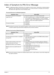
... Diskette/IDE drive connection/cables Diskette/IDE disk drives See "Undetermined Problems". Mainboard NOTE: Ensure the memory modules are installed properly and the contact leads are clean before diagnosing any system problems. Chapter 4 67 Blinking cursor only; system does not work... does not work . Its reading should be +12Vdc. Processor test failed. Its reading should be exactly set to Enabled. Incorrect memory size shown or repeated during POST. Index of Symptom-to-FRU Error Message NOTE: To diagnose a problem, first find the error...
... Diskette/IDE drive connection/cables Diskette/IDE disk drives See "Undetermined Problems". Mainboard NOTE: Ensure the memory modules are installed properly and the contact leads are clean before diagnosing any system problems. Chapter 4 67 Blinking cursor only; system does not work... does not work . Its reading should be +12Vdc. Processor test failed. Its reading should be exactly set to Enabled. Incorrect memory size shown or repeated during POST. Index of Symptom-to-FRU Error Message NOTE: To diagnose a problem, first find the error...


