
Service Guide
Page 14
Rear Panel No. Icon 1 2 3 4 5 6 7 8 9 10 11 12 13 14 15 16 17 18 Component Expansion slot (Photo shows graphics card and TV tuner card) Line-out jack Microphone/speaker-out/line-in jack S/PDIF port eSATA port USB 2.0 ports VGA monitor port HDMI port PS2 keyboard port Power connector Voltage selector switch Lock slot Key hole PS2 mouse port Gigabit LAN port (10/100/1000 Mbps) Rear speaker/surround out jack Center speaker/subwoofer jack Audio in or side speaker jack 6 Chapter 1
Rear Panel No. Icon 1 2 3 4 5 6 7 8 9 10 11 12 13 14 15 16 17 18 Component Expansion slot (Photo shows graphics card and TV tuner card) Line-out jack Microphone/speaker-out/line-in jack S/PDIF port eSATA port USB 2.0 ports VGA monitor port HDMI port PS2 keyboard port Power connector Voltage selector switch Lock slot Key hole PS2 mouse port Gigabit LAN port (10/100/1000 Mbps) Rear speaker/surround out jack Center speaker/subwoofer jack Audio in or side speaker jack 6 Chapter 1
Service Guide
Page 58
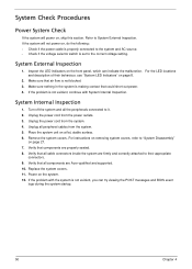
...try viewing the POST messages and BIOS event logs during the system startup. 50 Chapter 4 Remove the system covers. Verify that components are Acer-qualified and supported. 10. If the problem with System Internal Inspection. System External Inspection 1. Make sure nothing in the system is not ...are properly seated. 8. System Check Procedures Power System Check If the system will not power on, do the following: • Check if the power cable is properly connected to the system and AC source. • Check if the voltage selector switch is not evident, you can indicate the ...
...try viewing the POST messages and BIOS event logs during the system startup. 50 Chapter 4 Remove the system covers. Verify that components are Acer-qualified and supported. 10. If the problem with System Internal Inspection. System External Inspection 1. Make sure nothing in the system is not ...are properly seated. 8. System Check Procedures Power System Check If the system will not power on, do the following: • Check if the power cable is properly connected to the system and AC source. • Check if the voltage selector switch is not evident, you can indicate the ...

Service Guide
Page 74
Board Layout Mainboard No 1 2 3 4 5 6 7 8 9 10 11 12 13 14 66 Code LEDH1 N/A USBF3 USBF2 USBF1 PCIEX1 PCIE1 AUDIOF1 N/A N/A PWR1 U17 DIMM1-2 DIMM3-4 Description Power and switch LED cable connector Not available at this model Front USB connector Front USB connector Front USB connector PCI Express x16 slot PCI Express x1 slot Front audio connector Not available at this model Not available at this model 4-pin ATX power connector Processor socket DIMM slot DIMM slot Chapter 5
Board Layout Mainboard No 1 2 3 4 5 6 7 8 9 10 11 12 13 14 66 Code LEDH1 N/A USBF3 USBF2 USBF1 PCIEX1 PCIE1 AUDIOF1 N/A N/A PWR1 U17 DIMM1-2 DIMM3-4 Description Power and switch LED cable connector Not available at this model Front USB connector Front USB connector Front USB connector PCI Express x16 slot PCI Express x1 slot Front audio connector Not available at this model Not available at this model 4-pin ATX power connector Processor socket DIMM slot DIMM slot Chapter 5

Service Guide
Page 79
No. 1 2 3 4 5 6 7 8 9 10 11 12 13 14 15 16 17 18 19 20 21 22 23 24 25 26 Part Name C.A LED POWER SWITCH EJECT BUTTON FRONT BEZEL FRONT COVER IO DOOR IO DOOR BKT LENS POWER MAGNET 10*6*3 MIDDLE BEZEL ODD DOOR ODD LINK BKT ODD DOOR SPRING POWER BUTTON PROTECTFILM BEZEL-CVR PROTECTFILM EJECT PROTECTFILM IO DOOR PROTECTFILM MID BZL PROTECTFILM ODD DOOR PROTECTFILM POWER RUB ODD LINK SPG ODD BUTTON BOXER ASSEMBLY L CASE - ASM FRONT IO BRACKET ODD BRACKET HDD BRACKET Chapter 6 71 ASM ASSEMBLY U CASE -
No. 1 2 3 4 5 6 7 8 9 10 11 12 13 14 15 16 17 18 19 20 21 22 23 24 25 26 Part Name C.A LED POWER SWITCH EJECT BUTTON FRONT BEZEL FRONT COVER IO DOOR IO DOOR BKT LENS POWER MAGNET 10*6*3 MIDDLE BEZEL ODD DOOR ODD LINK BKT ODD DOOR SPRING POWER BUTTON PROTECTFILM BEZEL-CVR PROTECTFILM EJECT PROTECTFILM IO DOOR PROTECTFILM MID BZL PROTECTFILM ODD DOOR PROTECTFILM POWER RUB ODD LINK SPG ODD BUTTON BOXER ASSEMBLY L CASE - ASM FRONT IO BRACKET ODD BRACKET HDD BRACKET Chapter 6 71 ASM ASSEMBLY U CASE -


