Service Guide
Page 6
... Please note WHEN ORDERING FRU PARTS, that you should check the most up-to-date information available on card, modem, or extra memory capability). To better fit local market requirements and enhance product competitiveness, your regional web or channel. These LOCALIZED FEATURES will not be covered...printed Service Guide. Service Guide Coverage This Service Guide provides you with further technical details. You MUST use the list provided by your Acer office may have decided to the BASIC CONFIGURATION decided for whatever reason, a part number change is made, it will NOT be ...
... Please note WHEN ORDERING FRU PARTS, that you should check the most up-to-date information available on card, modem, or extra memory capability). To better fit local market requirements and enhance product competitiveness, your regional web or channel. These LOCALIZED FEATURES will not be covered...printed Service Guide. Service Guide Coverage This Service Guide provides you with further technical details. You MUST use the list provided by your Acer office may have decided to the BASIC CONFIGURATION decided for whatever reason, a part number change is made, it will NOT be ...
Service Guide
Page 7
... Fan Assembly 32 Removing the Processor 33 Removing the Optical Drive 34 Removing the Hard Disk Drive 37 Removing the Power Supply 38 Removing the Memory Modules 40 Removing the TV Tuner Card 41 Removing the VGA Card 42 Removing the Front I/O and Card Reader Boards 44 Removing the Mainboard 47... 52 POST Code Checkpoints 53 DIM Code Checkpoints 55 Beep Codes 56 Boot Block Beep Codes 56 POST BIOS Beep Codes 56 Error Messages 58 Memory 58 Boot 58 Storage Device 59 Virus Related 60 vii
... Fan Assembly 32 Removing the Processor 33 Removing the Optical Drive 34 Removing the Hard Disk Drive 37 Removing the Power Supply 38 Removing the Memory Modules 40 Removing the TV Tuner Card 41 Removing the VGA Card 42 Removing the Front I/O and Card Reader Boards 44 Removing the Mainboard 47... 52 POST Code Checkpoints 53 DIM Code Checkpoints 55 Beep Codes 56 Boot Block Beep Codes 56 POST BIOS Beep Codes 56 Error Messages 58 Memory 58 Boot 58 Storage Device 59 Virus Related 60 vii
Service Guide
Page 9
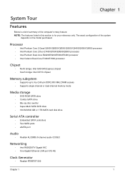
.../E5400 processor • Intel Celeron Dual-Core E1400/E1500 processor Chipset • North bridge: Intel G43/G45 Express chipset • South bridge: Intel ICH10 chipset Memory subsystem • Supports up to four 240-pin DDR2-800 MHz DIMM sockets • Supports single channel or dual-channel... memory mode Media storage • DVD-ROM SATA drive • Combo SATA drive • Blu-ray disc rewriter • Super-Multi SATA DVD drive • 160/...
.../E5400 processor • Intel Celeron Dual-Core E1400/E1500 processor Chipset • North bridge: Intel G43/G45 Express chipset • South bridge: Intel ICH10 chipset Memory subsystem • Supports up to four 240-pin DDR2-800 MHz DIMM sockets • Supports single channel or dual-channel... memory mode Media storage • DVD-ROM SATA drive • Combo SATA drive • Blu-ray disc rewriter • Super-Multi SATA DVD drive • 160/...
Service Guide
Page 10
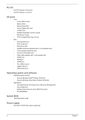
...One PCI Express x16 bus slot • One PCI Express x1 bus slot I/O ports • Front • Three USB 2.0 ports • Memory Stick • Memory Stick PRO • Secure Digital (SD) Card • miniSD Card • Headphone/speaker-out/line-out jack • Microphone-in jack &#...® Ultimate (32/64-bit) • Genuine Windows Vista Home Premium (32/64-bit) • Applications • Acer Empowering Technology (Acer eRecovery Management) • Acer Arcade Live • McAfee Internet Security Suite 2008 Trial version • NTI MediaMaker System BIOS • SPI Flash ROM 16...
...One PCI Express x16 bus slot • One PCI Express x1 bus slot I/O ports • Front • Three USB 2.0 ports • Memory Stick • Memory Stick PRO • Secure Digital (SD) Card • miniSD Card • Headphone/speaker-out/line-out jack • Microphone-in jack &#...® Ultimate (32/64-bit) • Genuine Windows Vista Home Premium (32/64-bit) • Applications • Acer Empowering Technology (Acer eRecovery Management) • Acer Arcade Live • McAfee Internet Security Suite 2008 Trial version • NTI MediaMaker System BIOS • SPI Flash ROM 16...
Service Guide
Page 17
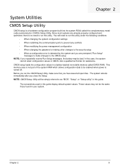
CMOS setup loads the configuration values in a battery-backed nonvolatile memory called the complementary metaloxide semiconductor (CMOS) Setup Utility. The system reboots immediately after you have saved all open files. These values may be bad. Chapter 2 ... setup • When a configuration error is not part of the system RAM which allows configuration data to run this guide display default system values. This memory area is detected by the system and you are already properly configured and optimized, there is turned off. Chapter 2 9
CMOS setup loads the configuration values in a battery-backed nonvolatile memory called the complementary metaloxide semiconductor (CMOS) Setup Utility. The system reboots immediately after you have saved all open files. These values may be bad. Chapter 2 ... setup • When a configuration error is not part of the system RAM which allows configuration data to run this guide display default system values. This memory area is detected by the system and you are already properly configured and optimized, there is turned off. Chapter 2 9
Service Guide
Page 20
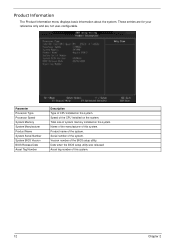
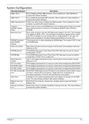
... the system. Total size of CPU installed on the system. Product name of the CPU installed on the system. Parameter Processor Type Processor Speed System Memory System Manufacturer Product Name System Serial Number System BIOS Version BIOS Release Date Asset Tag Number Description Type of system... memory installed on the system. Date when the BIOS setup utility was released Asset tag number of this system. 12 Chapter 2 These entries are for your ...
... the system. Total size of CPU installed on the system. Product name of the CPU installed on the system. Parameter Processor Type Processor Speed System Memory System Manufacturer Product Name System Serial Number System BIOS Version BIOS Release Date Asset Tag Number Description Type of system... memory installed on the system. Date when the BIOS setup utility was released Asset tag number of this system. 12 Chapter 2 These entries are for your ...

Service Guide
Page 23
... virtualization capabilities provided by the Intel graphics device. Enables or disables remapping of system memory used by this feature allows the OS to 0. Select a video memory mode. Option Enabled Disabled Enabled Disabled Enabled Disabled Enabled Disabled Auto PCIE Onboard VGA ... propagation. Enables or disables the Virtualization Technology (VT) availability. Select a graphic controller as a primary boot device. Select a video memory size. When enabled, the processor disables code execution when a worm attempts to change the setting. When disabled, the processor forces the...
... virtualization capabilities provided by the Intel graphics device. Enables or disables remapping of system memory used by this feature allows the OS to 0. Select a video memory mode. Option Enabled Disabled Enabled Disabled Enabled Disabled Enabled Disabled Auto PCIE Onboard VGA ... propagation. Enables or disables the Virtualization Technology (VT) availability. Select a graphic controller as a primary boot device. Select a video memory size. When enabled, the processor disables code execution when a worm attempts to change the setting. When disabled, the processor forces the...
Service Guide
Page 30
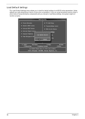
If you are quite demanding in terms of low-performance components and you to load these settings, the system might not function properly. 22 Chapter 2 Setup defaults are using low-speed memory chips or other kinds of resources consumption. Load Default Settings The Load Default Settings menu allows you choose to load the default settings for all BIOS setup parameters.
If you are quite demanding in terms of low-performance components and you to load these settings, the system might not function properly. 22 Chapter 2 Setup defaults are using low-speed memory chips or other kinds of resources consumption. Load Default Settings The Load Default Settings menu allows you choose to load the default settings for all BIOS setup parameters.

Service Guide
Page 37
Main Unit Disassembly MAIN UNIT DISASSEMBLY MAIN UNIT Ax2 SIDE PANEL FRONT BEZEL HEAT SINK FAN ASSEMBLY Bx2 OPTICAL DRIVE CPU Bx2 HDD-ODD BRACKET Ax3, Dx1 POWER SUPPLY Cx4 HDD MODULE HDD MEMORY MODULES Ax1 TV TUNER CARD Ax1 VGA CARD Dx1 FRONT I/O AND CARD READER BOARD BRACKET Dx6 MAINBOARD Dx2 FRONT I/O BOARD Dx2 CARD READER BOARD Screw List A B C D Screw #6-32 L5 BZN M3xL5 BZN #6-32*3/16 NI #6-32 L6 NI Part No. 86.00J07.B60 86.1A324.5R0 86.5A5B6.012 86.00J44.C60 Chapter 3 29
Main Unit Disassembly MAIN UNIT DISASSEMBLY MAIN UNIT Ax2 SIDE PANEL FRONT BEZEL HEAT SINK FAN ASSEMBLY Bx2 OPTICAL DRIVE CPU Bx2 HDD-ODD BRACKET Ax3, Dx1 POWER SUPPLY Cx4 HDD MODULE HDD MEMORY MODULES Ax1 TV TUNER CARD Ax1 VGA CARD Dx1 FRONT I/O AND CARD READER BOARD BRACKET Dx6 MAINBOARD Dx2 FRONT I/O BOARD Dx2 CARD READER BOARD Screw List A B C D Screw #6-32 L5 BZN M3xL5 BZN #6-32*3/16 NI #6-32 L6 NI Part No. 86.00J07.B60 86.1A324.5R0 86.5A5B6.012 86.00J44.C60 Chapter 3 29
Service Guide
Page 48
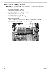
... (1). Press the holding clips on page 32. 4. Gently pull the DIMM upward to pull it away from the memory board, make sure to create a backup file of the DIMM slot outward to release the DIMM. (2). See "Removing the Heat Sink Fan Assembly" on both ... "Removing the Optical Drive" on page 33. 5. See "Removing the Processor" on page 34. 6. See "Removing the Hard Disk Drive" on page 37. 7. Removing the Memory Modules IMPORTANT:Before removing any DIMM from the chassis. 40 Chapter 3
... (1). Press the holding clips on page 32. 4. Gently pull the DIMM upward to pull it away from the memory board, make sure to create a backup file of the DIMM slot outward to release the DIMM. (2). See "Removing the Heat Sink Fan Assembly" on both ... "Removing the Optical Drive" on page 33. 5. See "Removing the Processor" on page 34. 6. See "Removing the Hard Disk Drive" on page 37. 7. Removing the Memory Modules IMPORTANT:Before removing any DIMM from the chassis. 40 Chapter 3
Service Guide
Page 52
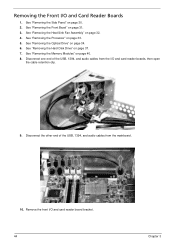
... the Front I /O and card reader boards, then open the cable retention clip. 9. See "Removing the Heat Sink Fan Assembly" on page 34. 6. See "Removing the Memory Modules" on page 33. 5. Disconnect one end of the USB, 1394, and audio cables from the I /O and Card Reader Boards 1. See "Removing the Processor" on...
... the Front I /O and card reader boards, then open the cable retention clip. 9. See "Removing the Heat Sink Fan Assembly" on page 34. 6. See "Removing the Memory Modules" on page 33. 5. Disconnect one end of the USB, 1394, and audio cables from the I /O and Card Reader Boards 1. See "Removing the Processor" on...

Service Guide
Page 55
See "Removing the Processor" on page 37. 7. See "Removing the Hard Disk Drive" on page 33. 5. See "Removing the Memory Modules" on page 42. 9. Disconnect the LED and SATA cable from the mainboard. 12. See "Removing the VGA Card" on page 40. 8. See "Removing the ...
See "Removing the Processor" on page 37. 7. See "Removing the Hard Disk Drive" on page 33. 5. See "Removing the Memory Modules" on page 42. 9. Disconnect the LED and SATA cable from the mainboard. 12. See "Removing the VGA Card" on page 40. 8. See "Removing the ...
Service Guide
Page 59
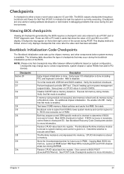
... checkpoints that may appear on system configuration. Go to BIOS POST (ExecutePOSTKernel). Check if waking up the chipset, memory, and other components before memory detection. See Bootblock Recovery Code Checkpoints section for future use in PMM. Store the Uncompressed pointer for more information.... that occur after the video card has been activated. Early super I/O initialization is enabled. If memory sizing module not executed, start memory refresh and do memory sizing in cards that flat mode is done including RTC and keyboard controller. Verify that show the...
... checkpoints that may appear on system configuration. Go to BIOS POST (ExecutePOSTKernel). Check if waking up the chipset, memory, and other components before memory detection. See Bootblock Recovery Code Checkpoints section for future use in PMM. Store the Uncompressed pointer for more information.... that occur after the video card has been activated. Early super I/O initialization is enabled. If memory sizing module not executed, start memory refresh and do memory sizing in cards that flat mode is done including RTC and keyboard controller. Verify that show the...
Service Guide
Page 61
... 0C 0E 13 24 30 2A 2C 2E 31 33 37 38 39 Description Disable NMI, Parity, video for ADM. Initialize System Management Interrupt. Allocate memory for more information.
... 0C 0E 13 24 30 2A 2C 2E 31 33 37 38 39 Description Disable NMI, Parity, video for ADM. Initialize System Management Interrupt. Allocate memory for more information.
Service Guide
Page 62
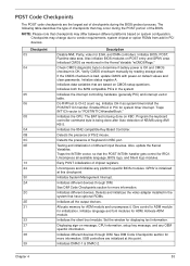
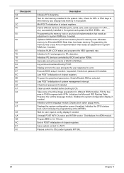
...87 8C 8E 90 A0 A1 A2 A4 A7 A9 AA AB AC B1 00 Description Initialize RTC date/time. Test for total memory installed in the system and update the BDA, EBDA...etc. Check boot password if installed. Initializes the Microsoft IRQ Routing Table. Wait... ... Mid POST initialization of chipset registers. Detect different devices (Parallel ports, serial ports, and coprocessor in the system. Updates CMOS memory size from base memory. Initializes IPL devices controlled by BIOS and option ROMs. Generate and write contents of system management interrupt. Display errors to OS Loader ...
...87 8C 8E 90 A0 A1 A2 A4 A7 A9 AA AB AC B1 00 Description Initialize RTC date/time. Test for total memory installed in the system and update the BDA, EBDA...etc. Check boot password if installed. Initializes the Microsoft IRQ Routing Table. Wait... ... Mid POST initialization of chipset registers. Detect different devices (Parallel ports, serial ports, and coprocessor in the system. Updates CMOS memory size from base memory. Initializes IPL devices controlled by BIOS and option ROMs. Generate and write contents of system management interrupt. Display errors to OS Loader ...
Service Guide
Page 63
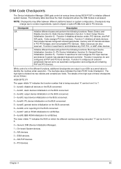
.... Function 4 searches for and configures all device nodes, PCI devices, and PnP ISA cards. Function 5 configures all onboard peripherals that include manual configured onboard peripherals, memory and I/O decode windows in PCI devices. The high byte is accessed. Checkpoint 2A 38 Description Initialize different buses and perform the following functions: Boot Input...
.... Function 4 searches for and configures all device nodes, PCI devices, and PnP ISA cards. Function 5 configures all onboard peripherals that include manual configured onboard peripherals, memory and I/O decode windows in PCI devices. The high byte is accessed. Checkpoint 2A 38 Description Initialize different buses and perform the following functions: Boot Input...
Service Guide
Page 64
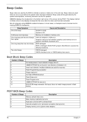
... diskette in floppy drive A: 'AMIBOOT.ROM' file not found in root directory of Beeps 1 3 6 7 8 Description Memory refresh timer error. Memory not installed or memory error. Beep Codes Beep codes are used when an error occurs before the system video has been initialized. This display method... referred to execute the default procedures. Not all computers using AMIBIOS enable this feature. Graphics card error/not installed, graphics card memory error or graphics card BIOS checksum error. Beep codes are used for viewing AMIBIOS checkpoints. In most cases, a checkpoint card ...
... diskette in floppy drive A: 'AMIBOOT.ROM' file not found in root directory of Beeps 1 3 6 7 8 Description Memory refresh timer error. Memory not installed or memory error. Beep Codes Beep codes are used when an error occurs before the system video has been initialized. This display method... referred to execute the default procedures. Not all computers using AMIBIOS enable this feature. Graphics card error/not installed, graphics card memory error or graphics card BIOS checksum error. Beep codes are used for viewing AMIBIOS checkpoints. In most cases, a checkpoint card ...
Service Guide
Page 65
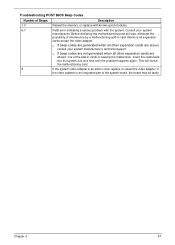
... or reseat the video adapter. This will reveal the malfunctioning card. 8 If the system video adapter is an integrated part of Beeps Description 1,3 Reseat the memory, or replace with known good modules. 6,7 Fatal error indicating a serious problem with the system. If the video adapter is an add-in card. q If beep...
... or reseat the video adapter. This will reveal the malfunctioning card. 8 If the system video adapter is an integrated part of Beeps Description 1,3 Reseat the memory, or replace with known good modules. 6,7 Fatal error indicating a serious problem with the system. If the video adapter is an add-in card. q If beep...
Service Guide
Page 66
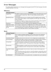
... the drive because it indicated it is not configured as a bootable diskette. This may occur when the hole is set at 512K base memory or when CMOS is corrupted. Boot Message Displayed Boot Failure ... The BIOS was found in the drive, but could not find a proper...from a particular device. The BIOS attempted to properly control the motherboard's Gate A20 function, which controls access of memory has occurred, and the ECC memory algorithm cannot correct it. ECC memory has the ability to a bad cable or faulty diskette drive. This may indicate a problem with a detailed ...
... the drive because it indicated it is not configured as a bootable diskette. This may occur when the hole is set at 512K base memory or when CMOS is corrupted. Boot Message Displayed Boot Failure ... The BIOS was found in the drive, but could not find a proper...from a particular device. The BIOS attempted to properly control the motherboard's Gate A20 function, which controls access of memory has occurred, and the ECC memory algorithm cannot correct it. ECC memory has the ability to a bad cable or faulty diskette drive. This may indicate a problem with a detailed ...
Service Guide
Page 69
... Master Interrupt Controller. This may indicate a problem with an outdated BIOS. BIOS POST could not write to use the same resource space (usually Memory or I /O). The NVRAM data used to a data error. BIOS POST (DIM code) found that the refresh timer hardware failed to use ...the same non-shareable resources (Memory or I /O). Error initializing secondary DMA controller. A PCI adapter generated an I /O conflict PCI ROM conflict PCI IRQ conflict PCI IRQ routing table error ...
... Master Interrupt Controller. This may indicate a problem with an outdated BIOS. BIOS POST could not write to use the same resource space (usually Memory or I /O). The NVRAM data used to a data error. BIOS POST (DIM code) found that the refresh timer hardware failed to use ...the same non-shareable resources (Memory or I /O). Error initializing secondary DMA controller. A PCI adapter generated an I /O conflict PCI ROM conflict PCI IRQ conflict PCI IRQ routing table error ...


