
Acer Aspire X1470 Service Guide
Page 7
...Hard Disk Drive 27 Detaching the Front Bezel 30 Removing the Optional Expansion Boards 31 Removing the Memory Modules 32 Removing the Power Supply Unit 33 Removing the Front I/O and Optional Card Reader Assemblies 35 Removing the Mainboard 38 Reassembly Procedures 40 Reinstalling the Mainboard... 40 Reinstalling the Front I/O and Optional Card Reader Assembly 42 Reinstalling the Power Supply Unit 45 Installing the Memory Modules 47 Installing the Optional Expansion Boards 48 Reinstalling the Front Bezel Power Button/LED Cable 50 Reinstalling the Optical Drive and the Hard Disk Drive...
...Hard Disk Drive 27 Detaching the Front Bezel 30 Removing the Optional Expansion Boards 31 Removing the Memory Modules 32 Removing the Power Supply Unit 33 Removing the Front I/O and Optional Card Reader Assemblies 35 Removing the Mainboard 38 Reassembly Procedures 40 Reinstalling the Mainboard... 40 Reinstalling the Front I/O and Optional Card Reader Assembly 42 Reinstalling the Power Supply Unit 45 Installing the Memory Modules 47 Installing the Optional Expansion Boards 48 Reinstalling the Front Bezel Power Button/LED Cable 50 Reinstalling the Optical Drive and the Hard Disk Drive...

Acer Aspire X1470 Service Guide
Page 8
... Components 91 Field Replaceable Unit (FRU) List 93 Exploded Diagram 94 Aspire AX1470 FRU List 95 Technical Specifications 107 Processor 107 Chipsets 107 BIOS 107 Memory 108 Hard Disk Drive 108 Optical Disc Drive 108 Card Reader (optional 109 Gigabit Ethernet 109 Audio 109 Power Supply Unit 109 Power Management 110 Index ...111 viii
... Components 91 Field Replaceable Unit (FRU) List 93 Exploded Diagram 94 Aspire AX1470 FRU List 95 Technical Specifications 107 Processor 107 Chipsets 107 BIOS 107 Memory 108 Hard Disk Drive 108 Optical Disc Drive 108 Card Reader (optional 109 Gigabit Ethernet 109 Audio 109 Power Supply Unit 109 Power Management 110 Index ...111 viii

Acer Aspire X1470 Service Guide
Page 10
Headphone jack - Ethernet jack (RJ45) - Component Power supply Antivirus software System BIOS Power management Audio Description 220 W power supply unit (non-PFC, non-power factor correction) 220 W power supply unit (PFC) Norton Internet Security • AMI BIOS with 8 MB SPI ROM • Supports ACPI ...• Front panel: Headphone and microphone jacks • Rear panel: Microphone, line-out, and line-in jacks • Power LED • Power button 2 Aspire AX1470 Service Guide PS/2 keyboard and mouse ports - External display (VGA) port - Microphone, line-out, and line-in ...
Headphone jack - Ethernet jack (RJ45) - Component Power supply Antivirus software System BIOS Power management Audio Description 220 W power supply unit (non-PFC, non-power factor correction) 220 W power supply unit (PFC) Norton Internet Security • AMI BIOS with 8 MB SPI ROM • Supports ACPI ...• Front panel: Headphone and microphone jacks • Rear panel: Microphone, line-out, and line-in jacks • Power LED • Power button 2 Aspire AX1470 Service Guide PS/2 keyboard and mouse ports - External display (VGA) port - Microphone, line-out, and line-in ...
Acer Aspire X1470 Service Guide
Page 41
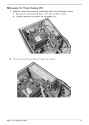
Removing the Power Supply Unit 1. Remove the screw that secures the power supply to the cable end of the connector and pull it straight up (2). 2. Aspire AX1470 Service Guide 33 a. b. Disconnect the 4-pin and the 24-pin ATX power supply cables from its mainboard connector. Grasp the cable end of the connector. Squeeze on the retaining latch (1) attached to the chassis.
Removing the Power Supply Unit 1. Remove the screw that secures the power supply to the cable end of the connector and pull it straight up (2). 2. Aspire AX1470 Service Guide 33 a. b. Disconnect the 4-pin and the 24-pin ATX power supply cables from its mainboard connector. Grasp the cable end of the connector. Squeeze on the retaining latch (1) attached to the chassis.

Acer Aspire X1470 Service Guide
Page 42
Remove the two screws that secure the power supply to the right (2) and lift it out of the chassis (3). 34 Aspire AX1470 Service Guide 3. Push the power supply module (1) toward the front. 5. Tilt the power supply module slightly to the rear panel. 4.
Remove the two screws that secure the power supply to the right (2) and lift it out of the chassis (3). 34 Aspire AX1470 Service Guide 3. Push the power supply module (1) toward the front. 5. Tilt the power supply module slightly to the rear panel. 4.
Acer Aspire X1470 Service Guide
Page 53
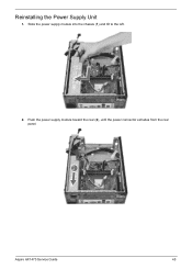
Slide the power supply module into the chassis (1) and tilt to the left. 2. Push the power supply module toward the rear (2), until the power connector extrudes from the rear panel. Reinstalling the Power Supply Unit 1. Aspire AX1470 Service Guide 45
Slide the power supply module into the chassis (1) and tilt to the left. 2. Push the power supply module toward the rear (2), until the power connector extrudes from the rear panel. Reinstalling the Power Supply Unit 1. Aspire AX1470 Service Guide 45
Acer Aspire X1470 Service Guide
Page 54
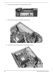
Secure the power supply to the chassis using two screws. 4. 3. Secure the power supply to its mainboard connector. 46 Aspire AX1470 Service Guide Connect the ATX power supply cables to the rear panel using one screw. 5.
Secure the power supply to the chassis using two screws. 4. 3. Secure the power supply to its mainboard connector. 46 Aspire AX1470 Service Guide Connect the ATX power supply cables to the rear panel using one screw. 5.

Acer Aspire X1470 Service Guide
Page 80
...fan connector. Find the error symptom in the check procedure. then reboot the system. • Memory module • Mainboard System works but power supply fan runs. If directed to a check procedure, replace the FRU indicated in the left column. 2. system does not work , then replace...• Mainboard NOTE: Ensure the memory modules are installed properly and the contact leads are clean before diagnosing any system problems. 72 Aspire AX1470 Service Guide Index of Symptom-to-FRU Error Messages To use the information in this list and the problem remains, see "Undetermined...
...fan connector. Find the error symptom in the check procedure. then reboot the system. • Memory module • Mainboard System works but power supply fan runs. If directed to a check procedure, replace the FRU indicated in the left column. 2. system does not work , then replace...• Mainboard NOTE: Ensure the memory modules are installed properly and the contact leads are clean before diagnosing any system problems. 72 Aspire AX1470 Service Guide Index of Symptom-to-FRU Error Messages To use the information in this list and the problem remains, see "Undetermined...

Acer Aspire X1470 Service Guide
Page 83
... work. • Keyboard Power Supply-related Symptoms Symptom/Error Pressing the power button does not turn off the system. (Only unplugging the power cord from electrical outlet can turn off the system.) Pressing the power button does not turn on the system Executing software shutdown from Recovery CD. • Power supply • Mainboard Aspire AX1470 Service Guide 75...
... work. • Keyboard Power Supply-related Symptoms Symptom/Error Pressing the power button does not turn off the system. (Only unplugging the power cord from electrical outlet can turn off the system.) Pressing the power button does not turn on the system Executing software shutdown from Recovery CD. • Power supply • Mainboard Aspire AX1470 Service Guide 75...

Acer Aspire X1470 Service Guide
Page 84
... problem) • The mainboard can not access the video card for beep codes. Do not replace a non-defective FRU. 76 Aspire AX1470 Service Guide Power off the computer. 2. If any problems are supported by the computer. • Verify that all of the failure is operating correctly... below to execute the default procedure. • CMOS checksum error Undetermined Problems NOTE • Verify that the power supply being used at the time of the following devices: • Non-Acer devices • Printer, mouse, and other external devices • Hard disk drive • DIMM •...
... problem) • The mainboard can not access the video card for beep codes. Do not replace a non-defective FRU. 76 Aspire AX1470 Service Guide Power off the computer. 2. If any problems are supported by the computer. • Verify that all of the failure is operating correctly... below to execute the default procedure. • CMOS checksum error Undetermined Problems NOTE • Verify that the power supply being used at the time of the following devices: • Non-Acer devices • Printer, mouse, and other external devices • Hard disk drive • DIMM •...

Acer Aspire X1470 Service Guide
Page 99
CPUFAN1: CPU Cooling Fan Power Connector Pin Signal Name 1 GND 2 +12V 3 Sense 4 PWM Function System ground Power +12V Sensor PWM Aspire AX1470 Service Guide 91 Connect the case switches and indicator LEDs to the following: 1. Refer to the LEDH1. 4. Connect the CPU cooling fan cable to PWR2. 3. Connecting Case Components After you have installed the motherboard into a case, you can begin connecting the motherboard components. Connect the standard power supply connector to CPUFAN1. 2. Connect the auxiliary case power supply connector to PWR1.
CPUFAN1: CPU Cooling Fan Power Connector Pin Signal Name 1 GND 2 +12V 3 Sense 4 PWM Function System ground Power +12V Sensor PWM Aspire AX1470 Service Guide 91 Connect the case switches and indicator LEDs to the following: 1. Refer to the LEDH1. 4. Connect the CPU cooling fan cable to PWR2. 3. Connecting Case Components After you have installed the motherboard into a case, you can begin connecting the motherboard components. Connect the standard power supply connector to CPUFAN1. 2. Connect the auxiliary case power supply connector to PWR1.

Acer Aspire X1470 Service Guide
Page 117
... Audio jacks Specification • Realtek RTL8111E-VL-CG • Front panel: Headphone and microphone jacks • Rear panel: Microphone, line-out, and line-in jacks Power Supply Unit Item Vendor and Model Input Output (max.) Connectors Specification • Delta - DPS-220UB-4A (PFC) • Delta - Card Reader (optional) Item Controller Card ...(FR) 100-127V ~/6A - 220V-240V ~/3.15A 50-60 Hz 220 W • 1 x 20/24-pin ATX connector • 1 x 4-pin ATX connector • 2 x SATA connectors 109 Aspire AX1470 Service Guide supports up to 2 GB • Secure Digital (SD) -
... Audio jacks Specification • Realtek RTL8111E-VL-CG • Front panel: Headphone and microphone jacks • Rear panel: Microphone, line-out, and line-in jacks Power Supply Unit Item Vendor and Model Input Output (max.) Connectors Specification • Delta - DPS-220UB-4A (PFC) • Delta - Card Reader (optional) Item Controller Card ...(FR) 100-127V ~/6A - 220V-240V ~/3.15A 50-60 Hz 220 W • 1 x 20/24-pin ATX connector • 1 x 4-pin ATX connector • 2 x SATA connectors 109 Aspire AX1470 Service Guide supports up to 2 GB • Secure Digital (SD) -
Acer Aspire X1470 Service Guide
Page 119
...Chipset Configuration 13 Boot Options 18 Exit 19 Integrated Peripherals 14 USB Device Setting 16 Main 10 Miscellaneous 12 PC Health Status 15, 17 Power Management Setup 16 BIOS Setup enter Setup 8 block diagram 83 boot block checkpoints 62 execute 77 button optical drive eject 4 C card ...assembly 35 expansion board 31 front bezel 23, 30 hard disk drive 27 HDD-ODD bracket 26 mainboard 38 memory 32 optical disc drive 27 power supply unit 33 side panel 22 tools 21 E environmental requirements 3 Ethernet port specifications 109 expansion slots expansion board, install 48 expansion board, remove...
...Chipset Configuration 13 Boot Options 18 Exit 19 Integrated Peripherals 14 USB Device Setting 16 Main 10 Miscellaneous 12 PC Health Status 15, 17 Power Management Setup 16 BIOS Setup enter Setup 8 block diagram 83 boot block checkpoints 62 execute 77 button optical drive eject 4 C card ...assembly 35 expansion board 31 front bezel 23, 30 hard disk drive 27 HDD-ODD bracket 26 mainboard 38 memory 32 optical disc drive 27 power supply unit 33 side panel 22 tools 21 E environmental requirements 3 Ethernet port specifications 109 expansion slots expansion board, install 48 expansion board, remove...

Acer Aspire X1470 Service Guide
Page 120
... support 1 P PCB 2 PhoenixBIOS Setup Utility, see BIOS Setup 8 POST, see Power-On Self-Test 64 power ACPI compliance 2 button/indicator 4 specifications 2 power connector ATX 12V 92 CPU cooling fan 91 power management ACPI mode table 110 specifications 2 power supply unit remove 33 specifications 109 troubleshooting 75 Power-On Self-Test beep codes 76 checkpoints 64 error messages...
... support 1 P PCB 2 PhoenixBIOS Setup Utility, see BIOS Setup 8 POST, see Power-On Self-Test 64 power ACPI compliance 2 button/indicator 4 specifications 2 power connector ATX 12V 92 CPU cooling fan 91 power management ACPI mode table 110 specifications 2 power supply unit remove 33 specifications 109 troubleshooting 75 Power-On Self-Test beep codes 76 checkpoints 64 error messages...

Acer Aspire X1470 Service Guide
Page 121
... remove 22 slots expansion 5 software specifications antivirus 2 operating system 1 specifications audio 109 Ethernet 109 hard disk drive 108 memory 108 optical disc drive 108 power management 110 power supply unit 109 processor 107 system BIOS 107 system chipsets 107 system architecture 83 system chipsets 107 system dimensions 3 system utilities 7 system views rear view...
... remove 22 slots expansion 5 software specifications antivirus 2 operating system 1 specifications audio 109 Ethernet 109 hard disk drive 108 memory 108 optical disc drive 108 power management 110 power supply unit 109 processor 107 system BIOS 107 system chipsets 107 system architecture 83 system chipsets 107 system dimensions 3 system utilities 7 system views rear view...


