
Acer Aspire X1470 Service Guide
Page 8
Table of Contents BIOS Update 78 Updating the BIOS in DOS Mode 78 Updating the BIOS in Windows Mode 79 Clearing CMOS 82 System Architecture 83 Block Diagram 83 Mainboard Layout 84 Jumper Setting 85 Internal header pin definition 86 ...Connector pin definition 87 Connecting Optional Devices 89 Connecting Case Components 91 Field Replaceable Unit (FRU) List 93 Exploded Diagram 94 Aspire...
Table of Contents BIOS Update 78 Updating the BIOS in DOS Mode 78 Updating the BIOS in Windows Mode 79 Clearing CMOS 82 System Architecture 83 Block Diagram 83 Mainboard Layout 84 Jumper Setting 85 Internal header pin definition 86 ...Connector pin definition 87 Connecting Optional Devices 89 Connecting Case Components 91 Field Replaceable Unit (FRU) List 93 Exploded Diagram 94 Aspire...

Acer Aspire X1470 Service Guide
Page 71
... super I/O. Boot Block Recovery Code Checkpoints The boot block recovery code gets control when the BIOS determines that a BIOS recovery is required because the user has forced the update or the BIOS checksum is tested. The following table describes the type of checkpoints that the found flash part.... Attempt to read from ARMD and ATAPI CDROM. Determine information about root directory of the BIOS. Verify that may occur during the boot block recovery portion of recovery media. Aspire AX1470 Service Guide 63 Checkpoint D6 D7 D8 D9 DA Description Both key sequence and OEM...
... super I/O. Boot Block Recovery Code Checkpoints The boot block recovery code gets control when the BIOS determines that a BIOS recovery is required because the user has forced the update or the BIOS checksum is tested. The following table describes the type of checkpoints that the found flash part.... Attempt to read from ARMD and ATAPI CDROM. Determine information about root directory of the BIOS. Verify that may occur during the boot block recovery portion of recovery media. Aspire AX1470 Service Guide 63 Checkpoint D6 D7 D8 D9 DA Description Both key sequence and OEM...

Acer Aspire X1470 Service Guide
Page 72
... that are based on CMOS setup questions. Initialize BIOS, POST, Runtime data area. Initialized CMOS as system timer.Install the POSTINT1Ch handler. Initialize status register A. Initialize CH-0 as mentioned in the system. Also, update the Kernel Variables. Uncompress all the output devices.... controlling hardware (generally PIC) and interrupt vector table. Detects and initializes the video adapter installed in the system. 64 Aspire AX1470 Service Guide Give control to ADM module for displaying text information. Set the window for initialization. Checkpoint 03 04 ...
... that are based on CMOS setup questions. Initialize BIOS, POST, Runtime data area. Initialized CMOS as system timer.Install the POSTINT1Ch handler. Initialize status register A. Initialize CH-0 as mentioned in the system. Also, update the Kernel Variables. Uncompress all the output devices.... controlling hardware (generally PIC) and interrupt vector table. Detects and initializes the video adapter installed in the system. 64 Aspire AX1470 Service Guide Give control to ADM module for displaying text information. Set the window for initialization. Checkpoint 03 04 ...

Acer Aspire X1470 Service Guide
Page 73
...90 A0 A1 A2 A4 A7 A8 A9 AA AB AC B1 00 Description Mid POST initialization of runtime image preparation for different BIOS modules. Updates CMOS memory size from base memory. Late POST initialization of chipset registers. Check boot password if installed. Displays the system configuration ...POST INT1Ch vector and INT09h vector. Initialize Int-13 and prepare for ACPI. Program the peripheral parameters. Aspire AX1470 Service Guide 65 Fill the free area in the system and update the BDA, EBDA...etc. Deinitializes the ADM module. Save system context for IPL detection. Programming the ...
...90 A0 A1 A2 A4 A7 A8 A9 AA AB AC B1 00 Description Mid POST initialization of runtime image preparation for different BIOS modules. Updates CMOS memory size from base memory. Late POST initialization of chipset registers. Check boot password if installed. Displays the system configuration ...POST INT1Ch vector and INT09h vector. Initialize Int-13 and prepare for ACPI. Program the peripheral parameters. Aspire AX1470 Service Guide 65 Fill the free area in the system and update the BDA, EBDA...etc. Deinitializes the ADM module. Save system context for IPL detection. Programming the ...

Acer Aspire X1470 Service Guide
Page 78
... timer test failed Interrupt Controller-1 error Interrupt Controller-2 error Description Error initializing primary DMA controller. If the BIOS detects possible virus activity, it will only be updated to a data error. This is no FLASH part (System uses a PROM or EPROM). The message ... an I /O resource conflict when configured by BIOS POST. This may indicate a problem with an outdated BIOS. BIOS could not find or load the CPU Microcode Update to the NVRAM block. This is enabled in a mainboard with system hardware. 70 Aspire AX1470 Service Guide POST error while trying to ...
... timer test failed Interrupt Controller-1 error Interrupt Controller-2 error Description Error initializing primary DMA controller. If the BIOS detects possible virus activity, it will only be updated to a data error. This is no FLASH part (System uses a PROM or EPROM). The message ... an I /O resource conflict when configured by BIOS POST. This may indicate a problem with an outdated BIOS. BIOS could not find or load the CPU Microcode Update to the NVRAM block. This is enabled in a mainboard with system hardware. 70 Aspire AX1470 Service Guide POST error while trying to ...
Acer Aspire X1470 Service Guide
Page 86
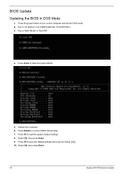
Reboot the computer. 6. Press Delete to flash the system BIOS. 5. Press Enter to run the CMOS Setup Utility. 7. Press F9 to load the system default settings. 8. Key in 'cd dostool'. (Go to DOS mode. 2. Press F9 to save the default settings and close the Setup utility. 10. Select Ok, then press Enter. 78 Aspire AX1470 Service Guide Key in 'flash1M.bat' or 'flash1M'. 4. Select Ok, then press Enter. 9. Press the power button to turn on the computer and boot to BIOS path like "A:\DOSTOOL") 3. BIOS Update Updating the BIOS in DOS Mode 1.
Reboot the computer. 6. Press Delete to flash the system BIOS. 5. Press Enter to run the CMOS Setup Utility. 7. Press F9 to load the system default settings. 8. Key in 'cd dostool'. (Go to DOS mode. 2. Press F9 to save the default settings and close the Setup utility. 10. Select Ok, then press Enter. 78 Aspire AX1470 Service Guide Key in 'flash1M.bat' or 'flash1M'. 4. Select Ok, then press Enter. 9. Press the power button to turn on the computer and boot to BIOS path like "A:\DOSTOOL") 3. BIOS Update Updating the BIOS in DOS Mode 1.

Acer Aspire X1470 Service Guide
Page 87
or 64-bit Windows OS. 1. Press the power button to BIOS path like "D:\WinTool\32") b. Key in Windows Mode This BIOS updating procedure is running a 32- Updating the BIOS in 'cd wintool\32'. (Go to turn on the computer. 2. Click Start | Command Prompt | Run as administrator. 3. Perform the steps below if your computer is for a computer running 32-bit Windows. Key in 'flash1M.bat' or 'flash1M'. Aspire AX1470 Service Guide 79 a.
or 64-bit Windows OS. 1. Press the power button to BIOS path like "D:\WinTool\32") b. Key in Windows Mode This BIOS updating procedure is running a 32- Updating the BIOS in 'cd wintool\32'. (Go to turn on the computer. 2. Click Start | Command Prompt | Run as administrator. 3. Perform the steps below if your computer is for a computer running 32-bit Windows. Key in 'flash1M.bat' or 'flash1M'. Aspire AX1470 Service Guide 79 a.
Acer Aspire X1470 Service Guide
Page 119
... 4 microphone jack, rear 5 specifications 109 troubleshooting 74 B Basic Input/Output System, see BIOS 7 beep codes 76 BIOS checkpoints 62 clear CMOS 82 CMOS RAM 7 configure 8 crisis recovery disk 77 overview 7 recovery 77 specifications 107 update, DOS mode 78 update, Windows mode 79 BIOS menus Advanced 11 Advanced Chipset Configuration 13 Boot Options 18 Exit 19...
... 4 microphone jack, rear 5 specifications 109 troubleshooting 74 B Basic Input/Output System, see BIOS 7 beep codes 76 BIOS checkpoints 62 clear CMOS 82 CMOS RAM 7 configure 8 crisis recovery disk 77 overview 7 recovery 77 specifications 107 update, DOS mode 78 update, Windows mode 79 BIOS menus Advanced 11 Advanced Chipset Configuration 13 Boot Options 18 Exit 19...

Acer Aspire X1470 Service Guide
Page 120
remove 23, 30 FRU list components list 95 exploded view 94 part number updates 93 H hard disk drive reinstall 51 remove 27 specifications 108 hardware exploded view 94 FRU list 93 specifications 107 troubleshooting 61 HDD, see hard disk ... 5 O ODD, see optical disc drive 1 operating system 1 optical disc drive reinstall 51 remove 27 specifications 108 troubleshooting 73 OS support 1 P PCB 2 PhoenixBIOS Setup Utility, see BIOS Setup 8 POST, see Power-On Self-Test 64 power ACPI compliance 2 button/indicator 4 specifications 2 power connector ATX 12V 92 CPU cooling fan 91 power management...
remove 23, 30 FRU list components list 95 exploded view 94 part number updates 93 H hard disk drive reinstall 51 remove 27 specifications 108 hardware exploded view 94 FRU list 93 specifications 107 troubleshooting 61 HDD, see hard disk ... 5 O ODD, see optical disc drive 1 operating system 1 optical disc drive reinstall 51 remove 27 specifications 108 troubleshooting 73 OS support 1 P PCB 2 PhoenixBIOS Setup Utility, see BIOS Setup 8 POST, see Power-On Self-Test 64 power ACPI compliance 2 button/indicator 4 specifications 2 power connector ATX 12V 92 CPU cooling fan 91 power management...

Acer Aspire X1470 Service Guide
Page 121
... system chipsets 107 system architecture 83 system chipsets 107 system dimensions 3 system utilities 7 system views rear view 5 system weight 3 T temperature operating 3 troubleshooting BIOS checkpoints 62 BIOS recovery 77 BIOS update 78 clearing CMOS 82 component failure 72 hardware diagnostic procedure 61 POST error indicators 66 U undetermined problems 76 USB ports front 5 V VGA port 5 video...
... system chipsets 107 system architecture 83 system chipsets 107 system dimensions 3 system utilities 7 system views rear view 5 system weight 3 T temperature operating 3 troubleshooting BIOS checkpoints 62 BIOS recovery 77 BIOS update 78 clearing CMOS 82 component failure 72 hardware diagnostic procedure 61 POST error indicators 66 U undetermined problems 76 USB ports front 5 V VGA port 5 video...


