Acer V5-471 Notebook Service Guide
Page 6
... Recommended Equipment 3-5 Replacement Requirements 3-5 Pre-disassembly Instructions 3-6 Disassembly Process 3-7 External Module Disassembly Process 3-8 External Modules Disassembly Flowchart 3-8 Removing the Battery Pack 3-9 Removing the DIMM Cover 3-10 Removing the DIMM Modules 3-11 Removing the ODD Module 3-12 Removing the Keyboard 3-15 Main Unit Disassembly Process 3-17 Main Unit Disassembly Flowchart 3-17...28 Removing the Thermal Module 3-31 Removing the DC In Module 3-33 Removing the Battery Connector 3-34 Removing the Speaker Module 3-35 Removing the LCD Module 3-37 vi
... Recommended Equipment 3-5 Replacement Requirements 3-5 Pre-disassembly Instructions 3-6 Disassembly Process 3-7 External Module Disassembly Process 3-8 External Modules Disassembly Flowchart 3-8 Removing the Battery Pack 3-9 Removing the DIMM Cover 3-10 Removing the DIMM Modules 3-11 Removing the ODD Module 3-12 Removing the Keyboard 3-15 Main Unit Disassembly Process 3-17 Main Unit Disassembly Flowchart 3-17...28 Removing the Thermal Module 3-31 Removing the DC In Module 3-33 Removing the Battery Connector 3-34 Removing the Speaker Module 3-35 Removing the LCD Module 3-37 vi

Acer V5-471 Notebook Service Guide
Page 7
... Board 3-41 Removing the LCD Panel 3-42 Removing the LCD FPC Cable 3-43 Removing the LCD Brackets 3-44 Removing the Microphone 3-45 LCD Module Reassembly Process 3-46 Reinstalling the Microphone 3-46 Reinstalling the LCD Brackets 3-47 Reinstalling the LCD FPC Cable 3-48 Reinstalling the LCD Panel 3-49 Reinstalling the ...72 Reinstalling the Keyboard 3-72 Reinstalling the ODD Module 3-74 Reinstalling the DIMM Modules 3-77 Reinstalling the DIMM Cover 3-78 Reinstalling the Battery Pack 3-79 CHAPTER 4 Troubleshooting Introduction 4-3 General Information 4-3 Power On Issues 4-4 vii
... Board 3-41 Removing the LCD Panel 3-42 Removing the LCD FPC Cable 3-43 Removing the LCD Brackets 3-44 Removing the Microphone 3-45 LCD Module Reassembly Process 3-46 Reinstalling the Microphone 3-46 Reinstalling the LCD Brackets 3-47 Reinstalling the LCD FPC Cable 3-48 Reinstalling the LCD Panel 3-49 Reinstalling the ...72 Reinstalling the Keyboard 3-72 Reinstalling the ODD Module 3-74 Reinstalling the DIMM Modules 3-77 Reinstalling the DIMM Cover 3-78 Reinstalling the Battery Pack 3-79 CHAPTER 4 Troubleshooting Introduction 4-3 General Information 4-3 Power On Issues 4-4 vii
Acer V5-471 Notebook Service Guide
Page 80
...Instructions 3-6 Disassembly Process 3-7 External Module Disassembly Process 3-8 External Modules Disassembly Flowchart 3-8 Removing the Battery Pack 3-9 Removing the DIMM Cover 3-10 Removing the DIMM Modules 3-11 Removing the ODD Module 3-12 Removing the Keyboard 3-15 Main Unit Disassembly Process 3-17 Main...LCD Module 3-37 LCD Module Disassembly Process 3-39 LCD Module Disassembly Flowchart 3-39 Removing the LCD Bezel 3-40 Removing the Camera Board 3-41 Removing the LCD Panel 3-42 Removing the LCD FPC Cable 3-43 Removing the LCD Brackets 3-44 Removing the Microphone 3-45 LCD...
...Instructions 3-6 Disassembly Process 3-7 External Module Disassembly Process 3-8 External Modules Disassembly Flowchart 3-8 Removing the Battery Pack 3-9 Removing the DIMM Cover 3-10 Removing the DIMM Modules 3-11 Removing the ODD Module 3-12 Removing the Keyboard 3-15 Main Unit Disassembly Process 3-17 Main...LCD Module 3-37 LCD Module Disassembly Process 3-39 LCD Module Disassembly Flowchart 3-39 Removing the LCD Bezel 3-40 Removing the Camera Board 3-41 Removing the LCD Panel 3-42 Removing the LCD FPC Cable 3-43 Removing the LCD Brackets 3-44 Removing the Microphone 3-45 LCD...
Acer V5-471 Notebook Service Guide
Page 81
Reinstalling the Camera Board 3-50 Reinstalling the LCD Bezel 3-51 Main Unit Reassembly Process 3-52 Reinstalling the LCD Module 3-52 Reinstalling the Speaker Module 3-54 Reinstalling the Battery Connector 3-56 Reinstalling the DC In Module 3-57 Reinstalling the Thermal Module 3-58 Reinstalling the .../Upper Case 3-70 External Module Reassembly Process 3-72 Reinstalling the Keyboard 3-72 Reinstalling the ODD Module 3-74 Reinstalling the DIMM Modules 3-77 Reinstalling the DIMM Cover 3-78 Reinstalling the Battery Pack 3-79 3-3
Reinstalling the Camera Board 3-50 Reinstalling the LCD Bezel 3-51 Main Unit Reassembly Process 3-52 Reinstalling the LCD Module 3-52 Reinstalling the Speaker Module 3-54 Reinstalling the Battery Connector 3-56 Reinstalling the DC In Module 3-57 Reinstalling the Thermal Module 3-58 Reinstalling the .../Upper Case 3-70 External Module Reassembly Process 3-72 Reinstalling the Keyboard 3-72 Reinstalling the ODD Module 3-74 Reinstalling the DIMM Modules 3-77 Reinstalling the DIMM Cover 3-78 Reinstalling the Battery Pack 3-79 3-3
Acer V5-471 Notebook Service Guide
Page 118
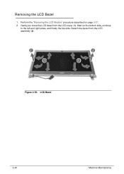
Start on page 3-37. 2. Detach the bezel from the LCD cover (1). LCD Bezel 3-40 Machine Maintenance Figure 3-50. Gently pry loose the LCD bezel from the LCD assembly (2). Removing the LCD Bezel 0 1. Perform the "Removing the LCD Module" procedure described on the bottom side, continue to the left and right sides, and finally the top side.
Start on page 3-37. 2. Detach the bezel from the LCD cover (1). LCD Bezel 3-40 Machine Maintenance Figure 3-50. Gently pry loose the LCD bezel from the LCD assembly (2). Removing the LCD Bezel 0 1. Perform the "Removing the LCD Module" procedure described on the bottom side, continue to the left and right sides, and finally the top side.

Acer V5-471 Notebook Service Guide
Page 119
Machine Maintenance 3-41 Disconnect the camera cable from the camera board. Camera Cable 3. Figure 3-52. Follow the local regulations for disposing this type of circuit board. Camera Board NOTE: NOTE: A circuit board that is >10 cm2 has been highlighted with a yellow rectangle in Figure 3-52. Figure 3-51. Gently pry the camera board off the LCD back cover. Perform the "Removing the LCD Bezel" procedure described on page 3-40. 2. Removing the Camera Board 0 1.
Machine Maintenance 3-41 Disconnect the camera cable from the camera board. Camera Cable 3. Figure 3-52. Follow the local regulations for disposing this type of circuit board. Camera Board NOTE: NOTE: A circuit board that is >10 cm2 has been highlighted with a yellow rectangle in Figure 3-52. Figure 3-51. Gently pry the camera board off the LCD back cover. Perform the "Removing the LCD Bezel" procedure described on page 3-40. 2. Removing the Camera Board 0 1.

Acer V5-471 Notebook Service Guide
Page 120
LCD Panel Screws Table 3-53. Release the LCD cable from the latch located near the hinge (1), then gently lift the LCD panel (2). 3-42 Figure 3-54. Remove the four screws securing the LCD panel to the LCD back cover. Screws Step LCD Panel Disassembly Screw M2 x L3 Quantity 4 Screw Type 3. Perform the "Removing the LCD Bezel" procedure described on page 3-40. 2. LCD Cable Machine Maintenance Figure 3-53. Removing the LCD Panel 0 1.
LCD Panel Screws Table 3-53. Release the LCD cable from the latch located near the hinge (1), then gently lift the LCD panel (2). 3-42 Figure 3-54. Remove the four screws securing the LCD panel to the LCD back cover. Screws Step LCD Panel Disassembly Screw M2 x L3 Quantity 4 Screw Type 3. Perform the "Removing the LCD Bezel" procedure described on page 3-40. 2. LCD Cable Machine Maintenance Figure 3-53. Removing the LCD Panel 0 1.

Acer V5-471 Notebook Service Guide
Page 122
LCD Bracket Screws Table 3-57. Detach the LCD bracket from the LCD back cover. LCD Bracket 3-44 Machine Maintenance Screws Step LCD Bracket Disassembly Screw M2 × L3 3. Removing the LCD Brackets 0 1. Remove the six screws securing the left and right LCD brackets to the LCD back cover. Perform the "Removing the LCD Panel" procedure described on page 3-42. 2. Figure 3-57. Quantity 6 Screw Type Figure 3-58.
LCD Bracket Screws Table 3-57. Detach the LCD bracket from the LCD back cover. LCD Bracket 3-44 Machine Maintenance Screws Step LCD Bracket Disassembly Screw M2 × L3 3. Removing the LCD Brackets 0 1. Remove the six screws securing the left and right LCD brackets to the LCD back cover. Perform the "Removing the LCD Panel" procedure described on page 3-42. 2. Figure 3-57. Quantity 6 Screw Type Figure 3-58.
Acer V5-471 Notebook Service Guide
Page 125
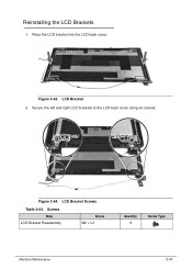
Figure 3-64. LCD Bracket Screws Table 3-64. Place the LCD bracket into the LCD back cover. Secure the left and right LCD brackets to the LCD back cover using six screws. Reinstalling the LCD Brackets 0 1. Figure 3-63. LCD Bracket 2. Screws Step LCD Bracket Reassembly Screw M2 × L3 Quantity 6 Screw Type Machine Maintenance 3-47
Figure 3-64. LCD Bracket Screws Table 3-64. Place the LCD bracket into the LCD back cover. Secure the left and right LCD brackets to the LCD back cover using six screws. Reinstalling the LCD Brackets 0 1. Figure 3-63. LCD Bracket 2. Screws Step LCD Bracket Reassembly Screw M2 × L3 Quantity 6 Screw Type Machine Maintenance 3-47

Acer V5-471 Notebook Service Guide
Page 127
LCD Cable 2. Figure 3-67. Screws Step LCD Panel Reassembly Screw M2 × L3 Machine Maintenance Quantity 4 Screw Type 3-49 Secure the LCD panel to the LCD back cover using four screws. LCD Panel Screws Table 3-68. Gently place the LCD panel into the LCD back cover (1), then insert the LCD cable into the latch located near the hinge (2). Figure 3-68. Reinstalling the LCD Panel 0 1.
LCD Cable 2. Figure 3-67. Screws Step LCD Panel Reassembly Screw M2 × L3 Machine Maintenance Quantity 4 Screw Type 3-49 Secure the LCD panel to the LCD back cover using four screws. LCD Panel Screws Table 3-68. Gently place the LCD panel into the LCD back cover (1), then insert the LCD cable into the latch located near the hinge (2). Figure 3-68. Reinstalling the LCD Panel 0 1.

Acer V5-471 Notebook Service Guide
Page 128
Gently place the camera board into the LCD back cover. Connect the camera cable to the camera board. Reinstalling the Camera Board 0 1. Figure 3-70. Camera Board 2. Figure 3-69. Camera Cable 3-50 Machine Maintenance
Gently place the camera board into the LCD back cover. Connect the camera cable to the camera board. Reinstalling the Camera Board 0 1. Figure 3-70. Camera Board 2. Figure 3-69. Camera Cable 3-50 Machine Maintenance


