Acer V5-471 Notebook Service Guide
Page 6
... Process 3-8 External Modules Disassembly Flowchart 3-8 Removing the Battery Pack 3-9 Removing the DIMM Cover 3-10 Removing the DIMM Modules 3-11 Removing the ODD Module 3-12 Removing the Keyboard 3-15 Main Unit Disassembly Process...Removing the Palmrest Module/Upper Case 3-18 Removing the Touchpad Board 3-21 Removing the Power Button Board 3-23 Removing the HDD Module 3-25 Removing the WLAN Module 3-26 Removing the Mainboard 3-28 Removing the Thermal Module 3-31 Removing the DC In Module 3-33 Removing the Battery Connector 3-34 Removing the Speaker Module 3-35 Removing...
... Process 3-8 External Modules Disassembly Flowchart 3-8 Removing the Battery Pack 3-9 Removing the DIMM Cover 3-10 Removing the DIMM Modules 3-11 Removing the ODD Module 3-12 Removing the Keyboard 3-15 Main Unit Disassembly Process...Removing the Palmrest Module/Upper Case 3-18 Removing the Touchpad Board 3-21 Removing the Power Button Board 3-23 Removing the HDD Module 3-25 Removing the WLAN Module 3-26 Removing the Mainboard 3-28 Removing the Thermal Module 3-31 Removing the DC In Module 3-33 Removing the Battery Connector 3-34 Removing the Speaker Module 3-35 Removing...

Acer V5-471 Notebook Service Guide
Page 7
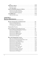
... Module Disassembly Process 3-39 LCD Module Disassembly Flowchart 3-39 Removing the LCD Bezel 3-40 Removing the Camera Board 3-41 Removing the LCD Panel 3-42 Removing the LCD FPC Cable 3-43 Removing the LCD Brackets 3-44 Removing the Microphone 3-45 LCD Module Reassembly Process 3-46 Reinstalling ...LCD Bezel 3-51 Main Unit Reassembly Process 3-52 Reinstalling the LCD Module 3-52 Reinstalling the Speaker Module 3-54 Reinstalling the Battery Connector 3-56 Reinstalling the DC In Module 3-57 Reinstalling the Thermal Module 3-58 Reinstalling the Mainboard 3-60 Reinstalling the WLAN...
... Module Disassembly Process 3-39 LCD Module Disassembly Flowchart 3-39 Removing the LCD Bezel 3-40 Removing the Camera Board 3-41 Removing the LCD Panel 3-42 Removing the LCD FPC Cable 3-43 Removing the LCD Brackets 3-44 Removing the Microphone 3-45 LCD Module Reassembly Process 3-46 Reinstalling ...LCD Bezel 3-51 Main Unit Reassembly Process 3-52 Reinstalling the LCD Module 3-52 Reinstalling the Speaker Module 3-54 Reinstalling the Battery Connector 3-56 Reinstalling the DC In Module 3-57 Reinstalling the Thermal Module 3-58 Reinstalling the Mainboard 3-60 Reinstalling the WLAN...
Acer V5-471 Notebook Service Guide
Page 25
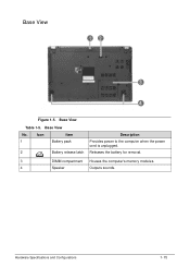
Icon Item 1 Battery pack 2 Battery release latch Description Provides power to the computer when the power cord is unplugged. Base View No. Releases the battery for removal. 3 DIMM compartment Houses the computer's memory modules. 4 Speaker Outputs sounds. Hardware Specifications and Configurations 1-15 Base View Table 1-5. Base View 0 Figure 1-5.
Icon Item 1 Battery pack 2 Battery release latch Description Provides power to the computer when the power cord is unplugged. Base View No. Releases the battery for removal. 3 DIMM compartment Houses the computer's memory modules. 4 Speaker Outputs sounds. Hardware Specifications and Configurations 1-15 Base View Table 1-5. Base View 0 Figure 1-5.
Acer V5-471 Notebook Service Guide
Page 77
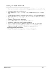
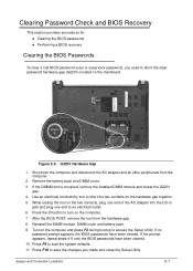
...and all other peripherals from the hardware gap. 8. If no password prompt appears, the BIOS passwords have been cleared. 10. After the BIOS POST, remove the tool from the computer. 2. Use an electrical conductivity tool to load the system defaults. 11. Press the button to an electrical outlet. 6.... the prompt appears, repeat steps 4-9 until the BIOS passwords have been cleared. Clearing the BIOS Passwords 0 1. If the DIMM2 slot is occupied, remove the installed DIMM module and locate the G2201 gap. 4. Remove the battery pack and DIMM cover. 3. Turn on the computer. 7.
...and all other peripherals from the hardware gap. 8. If no password prompt appears, the BIOS passwords have been cleared. 10. After the BIOS POST, remove the tool from the computer. 2. Use an electrical conductivity tool to load the system defaults. 11. Press the button to an electrical outlet. 6.... the prompt appears, repeat steps 4-9 until the BIOS passwords have been cleared. Clearing the BIOS Passwords 0 1. If the DIMM2 slot is occupied, remove the installed DIMM module and locate the G2201 gap. 4. Remove the battery pack and DIMM cover. 3. Turn on the computer. 7.
Acer V5-471 Notebook Service Guide
Page 80
... Unit Disassembly Flowchart 3-17 Removing the Palmrest Module/Upper Case 3-18 Removing the Touchpad Board 3-21 Removing the Power Button Board 3-23 Removing the HDD Module 3-25 Removing the WLAN Module 3-26 Removing the Mainboard 3-28 Removing the Thermal Module 3-31 Removing the DC In Module 3-33 Removing the Battery Connector 3-34 Removing the Speaker Module 3-35 Removing the LCD Module 3-37...
... Unit Disassembly Flowchart 3-17 Removing the Palmrest Module/Upper Case 3-18 Removing the Touchpad Board 3-21 Removing the Power Button Board 3-23 Removing the HDD Module 3-25 Removing the WLAN Module 3-26 Removing the Mainboard 3-28 Removing the Thermal Module 3-31 Removing the DC In Module 3-33 Removing the Battery Connector 3-34 Removing the Speaker Module 3-35 Removing the LCD Module 3-37...
Acer V5-471 Notebook Service Guide
Page 87
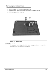
Figure 3-3. Turn the computer over so that the base is facing up. 2. Detach the battery and follow local regulations for disposal. Removing the Battery Pack 0 1. Slide and hold the battery release latch to release the battery pack (1). 3. Battery Pack NOTE: NOTE: The battery has been highlighted with the yellow rectangle in Figure 3-3. Machine Maintenance 3-9 Lift the battery pack from its bay (2).
Figure 3-3. Turn the computer over so that the base is facing up. 2. Detach the battery and follow local regulations for disposal. Removing the Battery Pack 0 1. Slide and hold the battery release latch to release the battery pack (1). 3. Battery Pack NOTE: NOTE: The battery has been highlighted with the yellow rectangle in Figure 3-3. Machine Maintenance 3-9 Lift the battery pack from its bay (2).
Acer V5-471 Notebook Service Guide
Page 88
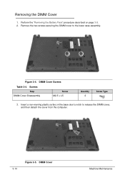
Removing the DIMM Cover 0 1. Perform the "Removing the Battery Pack" procedure described on the base door's notch to the lower case assembly. Screws Step DIMM Cover Disassembly Screw M2.5 × L5 Quantity 2 Screw Type 3. DIMM Cover Machine Maintenance Remove the two screws securing the DIMM cover to release the DIMM cover, and then detach the cover from the computer. 3-10 Figure 3-5. Insert a non-marring plastic scribe on page 3-9. 2. Figure 3-4. DIMM Cover Screws Table 3-4.
Removing the DIMM Cover 0 1. Perform the "Removing the Battery Pack" procedure described on the base door's notch to the lower case assembly. Screws Step DIMM Cover Disassembly Screw M2.5 × L5 Quantity 2 Screw Type 3. DIMM Cover Machine Maintenance Remove the two screws securing the DIMM cover to release the DIMM cover, and then detach the cover from the computer. 3-10 Figure 3-5. Insert a non-marring plastic scribe on page 3-9. 2. Figure 3-4. DIMM Cover Screws Table 3-4.
Acer V5-471 Notebook Service Guide
Page 90
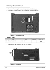
ODD Module Screw Table 3-7. ODD Module Machine Maintenance Remove the screw securing the ODD module to the lower case assembly. Figure 3-7. Gently pull out the ODD module from the ODD drive bay. 3-12 Figure 3-8. Screw Step ODD Module Disassembly Screw M2.5 × L5 Quantity 1 Screw Type 3. Perform the "Removing the Battery Pack" procedure described on page 3-9. 2. Removing the ODD Module 0 1.
ODD Module Screw Table 3-7. ODD Module Machine Maintenance Remove the screw securing the ODD module to the lower case assembly. Figure 3-7. Gently pull out the ODD module from the ODD drive bay. 3-12 Figure 3-8. Screw Step ODD Module Disassembly Screw M2.5 × L5 Quantity 1 Screw Type 3. Perform the "Removing the Battery Pack" procedure described on page 3-9. 2. Removing the ODD Module 0 1.
Acer V5-471 Notebook Service Guide
Page 93
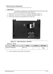
... the computer over and open the LCD panel. Removing the Keyboard 0 + IMPORTANT: The keyboard is easily warped or damaged during the removal process. Figure 3-12. Perform the "Removing the Battery Pack" procedure described on page 3-12. 3. Remove the screw securing the keyboard to use excessive force when removing. 1. Base Side Table 3-12. Upper Case Screw - Machine...
... the computer over and open the LCD panel. Removing the Keyboard 0 + IMPORTANT: The keyboard is easily warped or damaged during the removal process. Figure 3-12. Perform the "Removing the Battery Pack" procedure described on page 3-12. 3. Remove the screw securing the keyboard to use excessive force when removing. 1. Base Side Table 3-12. Upper Case Screw - Machine...
Acer V5-471 Notebook Service Guide
Page 112
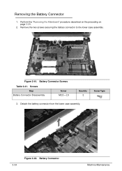
Figure 3-41. Remove the two screws securing the battery connector to the lower case assembly. Detach the battery connector from the lower case assembly. 3-34 Figure 3-42. Perform the "Removing the Mainboard" procedure described on the preceding on page 3-28. 2. Removing the Battery Connector 0 1. Battery Connector Screws Table 3-41. Screws Step Battery Connector Disassembly Screw M2.5 × L5 Quantity 2 Screw Type 3. Battery Connector Machine Maintenance
Figure 3-41. Remove the two screws securing the battery connector to the lower case assembly. Detach the battery connector from the lower case assembly. 3-34 Figure 3-42. Perform the "Removing the Mainboard" procedure described on the preceding on page 3-28. 2. Removing the Battery Connector 0 1. Battery Connector Screws Table 3-41. Screws Step Battery Connector Disassembly Screw M2.5 × L5 Quantity 2 Screw Type 3. Battery Connector Machine Maintenance
Acer V5-471 Notebook Service Guide
Page 164
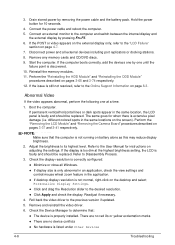
...that the computer is too dim at a time. 1. The same goes for instructions on battery alone as this may reduce display brightness. 2. 3. Connect the power cable and reboot the computer. 5. Perform the "Removing the LCD Module" and "Removing the Camera Board" procedures described on page 4-7. 7. If the display is not running on... all external devices including port replicators or docking stations. 8. Readjust if necessary. 4. Hold the power button for 10 seconds. 4. Drain stored power by removing the power cable and the battery pack. Reinstall the memory modules. 11.
...that the computer is too dim at a time. 1. The same goes for instructions on battery alone as this may reduce display brightness. 2. 3. Connect the power cable and reboot the computer. 5. Perform the "Removing the LCD Module" and "Removing the Camera Board" procedures described on page 4-7. 7. If the display is not running on... all external devices including port replicators or docking stations. 8. Readjust if necessary. 4. Hold the power button for 10 seconds. 4. Drain stored power by removing the power cable and the battery pack. Reinstall the memory modules. 11.
Acer V5-471 Notebook Service Guide
Page 177
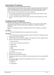
.... Determine if the problem has changed. 6. If an error is operating correctly. 1. If the problem does not recur, connect the removed devices one at a time until failing FRU is found , replace the FRU. 3. If the problem remains, replace the following devices: ...;Non-Acer devices Printer, mouse, and other external devices Battery pack Hard disk drive DIMM CD-ROM/Diskette drive Module ...
.... Determine if the problem has changed. 6. If an error is operating correctly. 1. If the problem does not recur, connect the removed devices one at a time until failing FRU is found , replace the FRU. 3. If the problem remains, replace the following devices: ...;Non-Acer devices Printer, mouse, and other external devices Battery pack Hard disk drive DIMM CD-ROM/Diskette drive Module ...
Acer V5-471 Notebook Service Guide
Page 197
.... Jumper and Connector Locations 5-7 Shut down the computer and disconnect the AC adapter and all other peripherals from the hardware gap. 8. Remove the battery pack and DIMM cover. 3. Press F9 to short the two contacts on the hardware gap together. 5. After the BIOS POST..., remove the tool from the computer. 2. Figure 2-5. While resting the tool on the computer. 7. Reinstall the DIMM module, DIMM cover and battery pack. 9. If no password prompt appears, the BIOS passwords have been cleared. 10...
.... Jumper and Connector Locations 5-7 Shut down the computer and disconnect the AC adapter and all other peripherals from the hardware gap. 8. Remove the battery pack and DIMM cover. 3. Press F9 to short the two contacts on the hardware gap together. 5. After the BIOS POST..., remove the tool from the computer. 2. Figure 2-5. While resting the tool on the computer. 7. Reinstall the DIMM module, DIMM cover and battery pack. 9. If no password prompt appears, the BIOS passwords have been cleared. 10...


