Service Guide
Page 6
... decided to extend the functionality of customer machines. add-on your regional Acer office to order FRU parts for repair and service of a machine (e.g. If, for Acer's "global" product offering. For ACER-AUTHORIZED SERVICE PROVIDERS, your regional offices or the responsible personnel/channel to ...Please note WHEN ORDERING FRU PARTS, that you should check the most up-to-date information available on card, modem, or extra memory capability). To better fit local market requirements and enhance product competitiveness, your regional office MAY have a DIFFERENT part number code to...
... decided to extend the functionality of customer machines. add-on your regional Acer office to order FRU parts for repair and service of a machine (e.g. If, for Acer's "global" product offering. For ACER-AUTHORIZED SERVICE PROVIDERS, your regional offices or the responsible personnel/channel to ...Please note WHEN ORDERING FRU PARTS, that you should check the most up-to-date information available on card, modem, or extra memory capability). To better fit local market requirements and enhance product competitiveness, your regional office MAY have a DIFFERENT part number code to...
Service Guide
Page 7
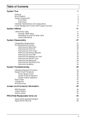
... 27 Disassembly Requirements 27 Pre-disassembly Procedure 28 Removing the Side Panel 29 Removing the CPU Fan 30 Removing the CPU Cooler 31 Removing the Memory Modules 32 Removing the Front D/B 33 Removing the Wireless Lan Card 34 Removing the S/PDIF Cover 35 Removing the Mainboard 36 Removing the Hard Disk... 41 Checkpoints 42 BIOS Recovery 44 Jumper and Connector Information 45 M/B Placement 45 Jumper Setting 46 Setting Jumper 46 FRU (Field Replaceable Unit) List 53 Aspire R3700 Exploded Diagram 54 Aspire R3700 FRU List 55 vii
... 27 Disassembly Requirements 27 Pre-disassembly Procedure 28 Removing the Side Panel 29 Removing the CPU Fan 30 Removing the CPU Cooler 31 Removing the Memory Modules 32 Removing the Front D/B 33 Removing the Wireless Lan Card 34 Removing the S/PDIF Cover 35 Removing the Mainboard 36 Removing the Hard Disk... 41 Checkpoints 42 BIOS Recovery 44 Jumper and Connector Information 45 M/B Placement 45 Jumper Setting 46 Setting Jumper 46 FRU (Field Replaceable Unit) List 53 Aspire R3700 Exploded Diagram 54 Aspire R3700 FRU List 55 vii

Service Guide
Page 8
... Intel Pine Trial-D platform design guide • Super I/O: ITE/8721 • Should support SST signal output PCB • 170mm*170mm (Proprietary) Memory subsystem • Socket Type: DDR III SO-DIMM connector • Socket Quantity: 2 • Only support single channel • Capacity support: ...• 1GB / 2 GB DDRIII 800 SO-DIMM support (follow Intel Spec.) • 1GB to 4GB Max memory support(follow Intel Spec.) • Design Criteria: • Should follow Pine Trail-D platform design guide • Should meet Pine Trail-D BIOS Specification...
... Intel Pine Trial-D platform design guide • Super I/O: ITE/8721 • Should support SST signal output PCB • 170mm*170mm (Proprietary) Memory subsystem • Socket Type: DDR III SO-DIMM connector • Socket Quantity: 2 • Only support single channel • Capacity support: ...• 1GB / 2 GB DDRIII 800 SO-DIMM support (follow Intel Spec.) • 1GB to 4GB Max memory support(follow Intel Spec.) • Design Criteria: • Should follow Pine Trail-D platform design guide • Should meet Pine Trail-D BIOS Specification...
Service Guide
Page 10
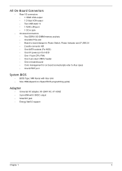
... VGA output • Two USB stack *2 • 1 RJ45 LAN port • 1 DC-in jack • On-board connectors • Two DDRIII SO-DIMM memory sockets • One Mini PCIe slot • Board to board design for Power Switch, Power Indicator and 2*USB 2.0 • 2 audio connector HD • One SATA... CMOS header • One on board buzzer • Color management for on board connecter(pls refer to Acer spec) • One S/PDIF port System BIOS • BIOS Type: AMI Kernel with Acer skin • Size: 8Mb(depend on chipset BIOS programming guide) Adapter • Universal AC adapter, 90...
... VGA output • Two USB stack *2 • 1 RJ45 LAN port • 1 DC-in jack • On-board connectors • Two DDRIII SO-DIMM memory sockets • One Mini PCIe slot • Board to board design for Power Switch, Power Indicator and 2*USB 2.0 • 2 audio connector HD • One SATA... CMOS header • One on board buzzer • Color management for on board connecter(pls refer to Acer spec) • One S/PDIF port System BIOS • BIOS Type: AMI Kernel with Acer skin • Size: 8Mb(depend on chipset BIOS programming guide) Adapter • Universal AC adapter, 90...
Service Guide
Page 15
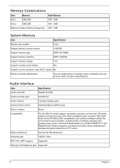
... 1 1GB,2GB 1GB ~2GB Slot 2 1GB,2GB 1GB ~2GB Maximum System Memory Supported 1GB ~4GB System Memory Item Specification Memory slot number 2 slot Support Memory size per socket 1GB,2GB Support memory type DDR3 SO-DIMM Support memory interface DDR3 800MHz Support memory voltage 1.5V Support to parity check feature Yes Support to error correction code (ECC...
... 1 1GB,2GB 1GB ~2GB Slot 2 1GB,2GB 1GB ~2GB Maximum System Memory Supported 1GB ~4GB System Memory Item Specification Memory slot number 2 slot Support Memory size per socket 1GB,2GB Support memory type DDR3 SO-DIMM Support memory interface DDR3 800MHz Support memory voltage 1.5V Support to parity check feature Yes Support to error correction code (ECC...
Service Guide
Page 18
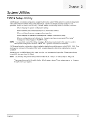
...loads the configuration values in CMOS. The screenshots used in this case, the system cannot retain configuration values in a battery-backed nonvolatile memory called the complementary metaloxide semiconductor (CMOS) Setup Utility. Chapter 2 System Utilities CMOS Setup Utility CMOS setup is a hardware configuration program built... system values. NOTE: CMOS Setup Utility will need to the security setup • When a configuration error is turned off. This memory area is not part of the system RAM which allows configuration data to run the CMOS Setup Utility, make changes to the CMOS...
...loads the configuration values in CMOS. The screenshots used in this case, the system cannot retain configuration values in a battery-backed nonvolatile memory called the complementary metaloxide semiconductor (CMOS) Setup Utility. Chapter 2 System Utilities CMOS Setup Utility CMOS setup is a hardware configuration program built... system values. NOTE: CMOS Setup Utility will need to the security setup • When a configuration error is turned off. This memory area is not part of the system RAM which allows configuration data to run the CMOS Setup Utility, make changes to the CMOS...
Service Guide
Page 21
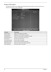
Parameter Processor Type Processor Speed System Memory System Manufacturer Product Name System Serial Number System BIOS Version BIOS Release Date Asset Tag Number Description Type of this system. Product name of the ... BIOS setup utility was released Asset tag number of CPU installed on the system. Version number of the system. Name of the manufacturer of system memory installed on the system. Total size of this system. 15 Chapter 2 Speed of the system. Serial number of the CPU installed on the system. Product...
Parameter Processor Type Processor Speed System Memory System Manufacturer Product Name System Serial Number System BIOS Version BIOS Release Date Asset Tag Number Description Type of this system. Product name of the ... BIOS setup utility was released Asset tag number of CPU installed on the system. Version number of the system. Name of the manufacturer of system memory installed on the system. Total size of this system. 15 Chapter 2 Speed of the system. Serial number of the CPU installed on the system. Product...
Service Guide
Page 30
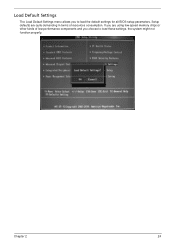
Setup defaults are using low-speed memory chips or other kinds of resources consumption. Chapter 2 24 If you are quite demanding in terms of low-performance components and you to load these settings, the system might not function properly. Load Default Settings The Load Default Settings menu allows you choose to load the default settings for all BIOS setup parameters.
Setup defaults are using low-speed memory chips or other kinds of resources consumption. Chapter 2 24 If you are quite demanding in terms of low-performance components and you to load these settings, the system might not function properly. Load Default Settings The Load Default Settings menu allows you choose to load the default settings for all BIOS setup parameters.

Service Guide
Page 38
Removing the Memory Modules 1. Remove the Memory from SO-DIMM socket. 32 Chapter 3 Release the hook as show below. 2.
Removing the Memory Modules 1. Remove the Memory from SO-DIMM socket. 32 Chapter 3 Release the hook as show below. 2.
Service Guide
Page 47
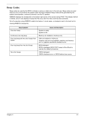
Beep codes will be generated by the BIOS to indicate a serious or fatal error to as the PC speaker. Memory not installed or memory error. BIOS is ready. One long beep then two short beep Two short beeps Cause and Description System is damaged, BIOS POST jumps to Boot ... Codes Beep codes are used by the system board speaker, commonly referred to the end user. CMOS damaged. Graphics card error/not installed, graphics card memory error or graphics card BIOS checksum error. AMIBIOS displays the checkpoints in the bottom right corner of the screen during POST.
Beep codes will be generated by the BIOS to indicate a serious or fatal error to as the PC speaker. Memory not installed or memory error. BIOS is ready. One long beep then two short beep Two short beeps Cause and Description System is damaged, BIOS POST jumps to Boot ... Codes Beep codes are used by the system board speaker, commonly referred to the end user. CMOS damaged. Graphics card error/not installed, graphics card memory error or graphics card BIOS checksum error. AMIBIOS displays the checkpoints in the bottom right corner of the screen during POST.
Service Guide
Page 48
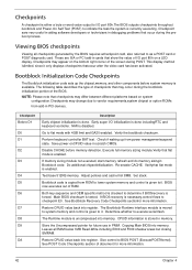
...the task the system is done. The following table describes the type of checkpoints that flat mode is enabled. Test base 512KB memory. Give control to as a POST card or POST diagnostic card. Adjust policies and cache first 8MB. See Bootblock Recovery Code ...sare very useful in aiding software developers or technicians in scratch CMOS. The Runtime module is available. Disable CACHE before system memory is uncompressed into register. Do additional chipsetinitialization. Viewing BIOS checkpoints Viewing all RAM below 1MB Read-Write including E000 and F000...
...the task the system is done. The following table describes the type of checkpoints that flat mode is enabled. Test base 512KB memory. Give control to as a POST card or POST diagnostic card. Adjust policies and cache first 8MB. See Bootblock Recovery Code ...sare very useful in aiding software developers or technicians in scratch CMOS. The Runtime module is available. Disable CACHE before system memory is uncompressed into register. Do additional chipsetinitialization. Viewing BIOS checkpoints Viewing all RAM below 1MB Read-Write including E000 and F000...
Service Guide
Page 61
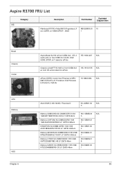
Aspire R3700 FRU List Category MB Description Part Number Exploded Diagram Item Mainboard R3700 nVidia NM10 Proprietary LF MB.SEM09.00 10 w/o eSATA, w/ HDMI,S/PDIF , D525 1 Bezel Chassis Cooler CPU Memory HDD Chapter 6 Aspire Bezel AL150 w/front USB2.0x2 , CR, 2 PZ.11900.207 N/A audio jack; w/ rear USB2.0x4, RJ45, ... Pineview D410/D510, VGA Nv Atom D525 (1.8G 1024K) Pineview-D KC.ADB01.52 N/A 5 Memory SAMSUNG SO-DIMM DDRIII 1333 1GB M471B2873FHS-CH9 LF 128*8 46nm KN.1GB0B.03 N/A 5 Memory UNIFOSA SO-DIMM DDRIII 1333 1GB GU672203EP0200 LF 128*8 0.065um KN.1GB0H.01 7 KINGSTON SO...
Aspire R3700 FRU List Category MB Description Part Number Exploded Diagram Item Mainboard R3700 nVidia NM10 Proprietary LF MB.SEM09.00 10 w/o eSATA, w/ HDMI,S/PDIF , D525 1 Bezel Chassis Cooler CPU Memory HDD Chapter 6 Aspire Bezel AL150 w/front USB2.0x2 , CR, 2 PZ.11900.207 N/A audio jack; w/ rear USB2.0x4, RJ45, ... Pineview D410/D510, VGA Nv Atom D525 (1.8G 1024K) Pineview-D KC.ADB01.52 N/A 5 Memory SAMSUNG SO-DIMM DDRIII 1333 1GB M471B2873FHS-CH9 LF 128*8 46nm KN.1GB0B.03 N/A 5 Memory UNIFOSA SO-DIMM DDRIII 1333 1GB GU672203EP0200 LF 128*8 0.065um KN.1GB0H.01 7 KINGSTON SO...


