Service Guide
Page 6
...Guide. If, for whatever reason, a part number change is made, it will NOT be noted in this printed Service Guide. For ACER-AUTHORIZED SERVICE PROVIDERS, your regional offices or the responsible personnel/channel to provide you with all technical information relating to those given in the...BASIC CONFIGURATION decided for repair and service of customer machines. In such cases, please contact your Acer office may have decided to -date information available on card, modem, or extra memory capability). FRU Information Please note WHEN ORDERING FRU PARTS, that you should check the most up...
...Guide. If, for whatever reason, a part number change is made, it will NOT be noted in this printed Service Guide. For ACER-AUTHORIZED SERVICE PROVIDERS, your regional offices or the responsible personnel/channel to provide you with all technical information relating to those given in the...BASIC CONFIGURATION decided for repair and service of customer machines. In such cases, please contact your Acer office may have decided to -date information available on card, modem, or extra memory capability). FRU Information Please note WHEN ORDERING FRU PARTS, that you should check the most up...
Service Guide
Page 7
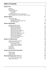
... 27 Disassembly Requirements 27 Pre-disassembly Procedure 28 Removing the Side Panel 29 Removing the CPU Fan 30 Removing the CPU Cooler 31 Removing the Memory Modules 32 Removing the Front D/B 33 Removing the Wireless Lan Card 34 Removing the S/PDIF Cover 35 Removing the Mainboard 36 Removing the Hard Disk... 41 Checkpoints 42 BIOS Recovery 44 Jumper and Connector Information 45 M/B Placement 45 Jumper Setting 46 Setting Jumper 46 FRU (Field Replaceable Unit) List 53 Aspire R3700 Exploded Diagram 54 Aspire R3700 FRU List 55 vii
... 27 Disassembly Requirements 27 Pre-disassembly Procedure 28 Removing the Side Panel 29 Removing the CPU Fan 30 Removing the CPU Cooler 31 Removing the Memory Modules 32 Removing the Front D/B 33 Removing the Wireless Lan Card 34 Removing the S/PDIF Cover 35 Removing the Mainboard 36 Removing the Hard Disk... 41 Checkpoints 42 BIOS Recovery 44 Jumper and Connector Information 45 M/B Placement 45 Jumper Setting 46 Setting Jumper 46 FRU (Field Replaceable Unit) List 53 Aspire R3700 Exploded Diagram 54 Aspire R3700 FRU List 55 vii

Service Guide
Page 8
... Intel Pine Trial-D platform design guide • Super I/O: ITE/8721 • Should support SST signal output PCB • 170mm*170mm (Proprietary) Memory subsystem • Socket Type: DDR III SO-DIMM connector • Socket Quantity: 2 • Only support single channel • Capacity support: ...• 1GB / 2 GB DDRIII 800 SO-DIMM support (follow Intel Spec.) • 1GB to 4GB Max memory support(follow Intel Spec.) • Design Criteria: • Should follow Pine Trail-D platform design guide • Should meet Pine Trail-D BIOS Specification...
... Intel Pine Trial-D platform design guide • Super I/O: ITE/8721 • Should support SST signal output PCB • 170mm*170mm (Proprietary) Memory subsystem • Socket Type: DDR III SO-DIMM connector • Socket Quantity: 2 • Only support single channel • Capacity support: ...• 1GB / 2 GB DDRIII 800 SO-DIMM support (follow Intel Spec.) • 1GB to 4GB Max memory support(follow Intel Spec.) • Design Criteria: • Should follow Pine Trail-D platform design guide • Should meet Pine Trail-D BIOS Specification...
Service Guide
Page 10
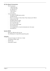
... VGA output • Two USB stack *2 • 1 RJ45 LAN port • 1 DC-in jack • On-board connectors • Two DDRIII SO-DIMM memory sockets • One Mini PCIe slot • Board to board design for Power Switch, Power Indicator and 2*USB 2.0 • 2 audio connector HD • One SATA... CMOS header • One on board buzzer • Color management for on board connecter(pls refer to Acer spec) • One S/PDIF port System BIOS • BIOS Type: AMI Kernel with Acer skin • Size: 8Mb(depend on chipset BIOS programming guide) Adapter • Universal AC adapter, 90...
... VGA output • Two USB stack *2 • 1 RJ45 LAN port • 1 DC-in jack • On-board connectors • Two DDRIII SO-DIMM memory sockets • One Mini PCIe slot • Board to board design for Power Switch, Power Indicator and 2*USB 2.0 • 2 audio connector HD • One SATA... CMOS header • One on board buzzer • Color management for on board connecter(pls refer to Acer spec) • One S/PDIF port System BIOS • BIOS Type: AMI Kernel with Acer skin • Size: 8Mb(depend on chipset BIOS programming guide) Adapter • Universal AC adapter, 90...
Service Guide
Page 15
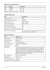
... 1 1GB,2GB 1GB ~2GB Slot 2 1GB,2GB 1GB ~2GB Maximum System Memory Supported 1GB ~4GB System Memory Item Specification Memory slot number 2 slot Support Memory size per socket 1GB,2GB Support memory type DDR3 SO-DIMM Support memory interface DDR3 800MHz Support memory voltage 1.5V Support to parity check feature Yes Support to error correction code (ECC...
... 1 1GB,2GB 1GB ~2GB Slot 2 1GB,2GB 1GB ~2GB Maximum System Memory Supported 1GB ~4GB System Memory Item Specification Memory slot number 2 slot Support Memory size per socket 1GB,2GB Support memory type DDR3 SO-DIMM Support memory interface DDR3 800MHz Support memory voltage 1.5V Support to parity check feature Yes Support to error correction code (ECC...
Service Guide
Page 18
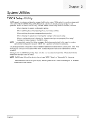
...default system values. Before you repeatedly receive Run Setup messages, the battery may not be bad. The screenshots used in a battery-backed nonvolatile memory called the complementary metaloxide semiconductor (CMOS) Setup Utility. Ask a qualified technician for assistance. In this utility under the following conditions. •...immediately after you have saved all open files. These values may be the same those found in CMOS. Chapter 2 12 This memory area is not part of the system RAM which allows configuration data to be simply referred to run this guide. NOTE: CMOS ...
...default system values. Before you repeatedly receive Run Setup messages, the battery may not be bad. The screenshots used in a battery-backed nonvolatile memory called the complementary metaloxide semiconductor (CMOS) Setup Utility. Ask a qualified technician for assistance. In this utility under the following conditions. •...immediately after you have saved all open files. These values may be the same those found in CMOS. Chapter 2 12 This memory area is not part of the system RAM which allows configuration data to be simply referred to run this guide. NOTE: CMOS ...
Service Guide
Page 21
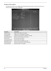
Total size of the system. Product name of system memory installed on the system. Speed of this system. 15 Chapter 2 Name of the manufacturer of the CPU installed on the system. Serial number of this ...system. Date when the BIOS setup utility was released Asset tag number of the system. Parameter Processor Type Processor Speed System Memory System Manufacturer Product Name System Serial Number System BIOS Version BIOS Release Date Asset Tag Number Description Type of the BIOS setup utility. These entries...
Total size of the system. Product name of system memory installed on the system. Speed of this system. 15 Chapter 2 Name of the manufacturer of the CPU installed on the system. Serial number of this ...system. Date when the BIOS setup utility was released Asset tag number of the system. Parameter Processor Type Processor Speed System Memory System Manufacturer Product Name System Serial Number System BIOS Version BIOS Release Date Asset Tag Number Description Type of the BIOS setup utility. These entries...
Service Guide
Page 30
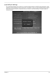
Load Default Settings The Load Default Settings menu allows you choose to load the default settings for all BIOS setup parameters. If you are quite demanding in terms of low-performance components and you to load these settings, the system might not function properly. Chapter 2 24 Setup defaults are using low-speed memory chips or other kinds of resources consumption.
Load Default Settings The Load Default Settings menu allows you choose to load the default settings for all BIOS setup parameters. If you are quite demanding in terms of low-performance components and you to load these settings, the system might not function properly. Chapter 2 24 Setup defaults are using low-speed memory chips or other kinds of resources consumption.

Service Guide
Page 38
Removing the Memory Modules 1. Release the hook as show below. 2. Remove the Memory from SO-DIMM socket. 32 Chapter 3
Removing the Memory Modules 1. Release the hook as show below. 2. Remove the Memory from SO-DIMM socket. 32 Chapter 3
Service Guide
Page 47
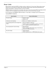
... feature. Beep Symptom One short beep Continuous one long beep One long beep and two short beeps then repeat. Memory not installed or memory error. CMOS damaged. Graphics card error/not installed, graphics card memory error or graphics card BIOS checksum error. BIOS damaged. CMOS checksum error or CMOS battery loss occurs. This...
... feature. Beep Symptom One short beep Continuous one long beep One long beep and two short beeps then repeat. Memory not installed or memory error. CMOS damaged. Graphics card error/not installed, graphics card memory error or graphics card BIOS checksum error. BIOS damaged. CMOS checksum error or CMOS battery loss occurs. This...
Service Guide
Page 48
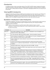
... Description Early chipset initialization is necessary,control flows to checkpoint E0. Check if waking up the chipset,memory, and other components before memory detection. Bootblock code is copied from power managementsuspend state. If BIOS recovery is done. See Bootblock Recovery...NOTE: Please note that show the value of checkpoints that occur during the preboot process. If memory sizing module not executed, start memory refresh and do memory sizingin Bootblock code. Verifythat flat mode is disabled. Store the Uncompressed pointer for more information. Copying...
... Description Early chipset initialization is necessary,control flows to checkpoint E0. Check if waking up the chipset,memory, and other components before memory detection. Bootblock code is copied from power managementsuspend state. If BIOS recovery is done. See Bootblock Recovery...NOTE: Please note that show the value of checkpoints that occur during the preboot process. If memory sizing module not executed, start memory refresh and do memory sizingin Bootblock code. Verifythat flat mode is disabled. Store the Uncompressed pointer for more information. Copying...
Service Guide
Page 61
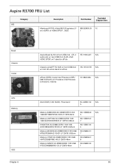
...2GB HMT325S6BFR8C-H9 LF 256*8 46nm KN.2GB0G.01 8 Memory NANYA SO-DIMM DDRIII 1333 2GB NT2GC64B88B0NS-CG LF 256*8 46nm KN.2GB03.02 1 55 Aspire R3700 FRU List Category MB Description Part Number Exploded Diagram Item Mainboard R3700 nVidia NM10 Proprietary LF MB.SEM09.00 10 w/o eSATA,... w/ HDMI,S/PDIF , D525 1 Bezel Chassis Cooler CPU Memory HDD Chapter 6 Aspire Bezel AL150 w/front USB2.0x2 , CR, 2...
...2GB HMT325S6BFR8C-H9 LF 256*8 46nm KN.2GB0G.01 8 Memory NANYA SO-DIMM DDRIII 1333 2GB NT2GC64B88B0NS-CG LF 256*8 46nm KN.2GB03.02 1 55 Aspire R3700 FRU List Category MB Description Part Number Exploded Diagram Item Mainboard R3700 nVidia NM10 Proprietary LF MB.SEM09.00 10 w/o eSATA,... w/ HDMI,S/PDIF , D525 1 Bezel Chassis Cooler CPU Memory HDD Chapter 6 Aspire Bezel AL150 w/front USB2.0x2 , CR, 2...


