Service Guide
Page 7
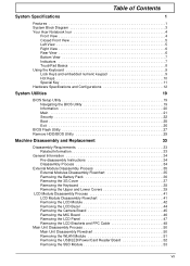
Table of Contents System Specifications 1 Features 1 System Block Diagram 3 Your Acer Notebook tour 4 Front View 4 Closed Front View 5 Left View 5 Right View 6 Rear View 6 Bottom View 7 Indicators 7 ...Main 21 Security 22 Boot 25 Exit 26 BIOS Flash Utility 27 Remove HDD/BIOS Utility 29 Machine Disassembly and Replacement 33 Disassembly Requirements 33 Related Information 33 General Information 34 Pre-disassembly Instructions 34 Disassembly Process 34 External Module ... WLAN Module 51 Removing the USB/LED/Power/Card Reader Board 52 Removing the SSD Module 53 VII
Table of Contents System Specifications 1 Features 1 System Block Diagram 3 Your Acer Notebook tour 4 Front View 4 Closed Front View 5 Left View 5 Right View 6 Rear View 6 Bottom View 7 Indicators 7 ...Main 21 Security 22 Boot 25 Exit 26 BIOS Flash Utility 27 Remove HDD/BIOS Utility 29 Machine Disassembly and Replacement 33 Disassembly Requirements 33 Related Information 33 General Information 34 Pre-disassembly Instructions 34 Disassembly Process 34 External Module ... WLAN Module 51 Removing the USB/LED/Power/Card Reader Board 52 Removing the SSD Module 53 VII
Service Guide
Page 43
The product previews seen in size. Chapter 3 33 Machine Disassembly and Replacement Chapter 3 This chapter contains step-by-step procedures on how to avoid mismatch when putting back the components. Related Information Please note that the images ..., group the screws with the corresponding components to disassemble the notebook computer for the different components vary in the disassembly procedures may differ slightly from a SSD SKU.
The product previews seen in size. Chapter 3 33 Machine Disassembly and Replacement Chapter 3 This chapter contains step-by-step procedures on how to avoid mismatch when putting back the components. Related Information Please note that the images ..., group the screws with the corresponding components to disassemble the notebook computer for the different components vary in the disassembly procedures may differ slightly from a SSD SKU.
Service Guide
Page 77
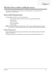
Main Module Reassembly Procedure Replacing the Thermal Module 1. Connect the Fan cable to the socket. 2. The modules are optional components. 1. Replace the Fan module on the Mainboard. 2. Replacing the DIMM Module IMPORTANT:The Aspire one SSD SKU does not come standard with number 1. 3. Insert DIMM1 in the order shown, starting with DIMM modules. Chapter 3 67 Press down to locate DIMM correctly. Replace the three screws in to the Mainboard.
Main Module Reassembly Procedure Replacing the Thermal Module 1. Connect the Fan cable to the socket. 2. The modules are optional components. 1. Replace the Fan module on the Mainboard. 2. Replacing the DIMM Module IMPORTANT:The Aspire one SSD SKU does not come standard with number 1. 3. Insert DIMM1 in the order shown, starting with DIMM modules. Chapter 3 67 Press down to locate DIMM correctly. Replace the three screws in to the Mainboard.
Service Guide
Page 81
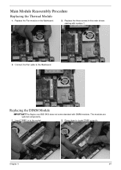
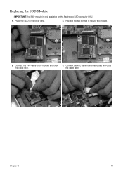
Replace the two screws to the mainboard and close 4. Replacing the SDD Module IMPORTANT:The SSD module is only available on the Aspire one SSD computer SKU. 1. Connect the FFC cable to the module and close the cable latch. Place the SDD in the lower case. 2. the cable latch. Connect the FFC cable to secure the module. 3. Chapter 3 71
Replace the two screws to the mainboard and close 4. Replacing the SDD Module IMPORTANT:The SSD module is only available on the Aspire one SSD computer SKU. 1. Connect the FFC cable to the module and close the cable latch. Place the SDD in the lower case. 2. the cable latch. Connect the FFC cable to secure the module. 3. Chapter 3 71
Service Guide
Page 82
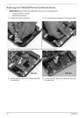
Connect the FFC cable to the module and close the cable latch. Replace the three or four screws (depending on SKU) to the board. 2. the cable latch. 72 Chapter 3 Replacing the USB/LED/Power/Card Reader Board IMPORTANT:Before installing the USB board, take care of the following items: • Check that LED isn`t broken • SLIDER work smoothly 1. Connect the cable to secure the module. Turn the board over and place it in the lower case. 3. HDD SKU SSD SKU 4. Connect the FFC cable to the mainboard and close 5.
Connect the FFC cable to the module and close the cable latch. Replace the three or four screws (depending on SKU) to the board. 2. the cable latch. 72 Chapter 3 Replacing the USB/LED/Power/Card Reader Board IMPORTANT:Before installing the USB board, take care of the following items: • Check that LED isn`t broken • SLIDER work smoothly 1. Connect the cable to secure the module. Turn the board over and place it in the lower case. 3. HDD SKU SSD SKU 4. Connect the FFC cable to the mainboard and close 5.

