Service Guide
Page 7
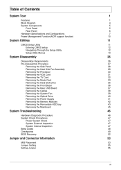
... 40 41 42 43 45 System Troubleshooting Hardware Diagnostic Procedure System Check Procedures Power System Check System External Inspection System Internal Inspection Beep Codes Checkpoints BIOS Recovery 46 46 47 47 47 47 48 49 52 Jumper and Connector Information M/B Placement Jumper Setting Setting Jumper 53 53 55 55 vii
... 40 41 42 43 45 System Troubleshooting Hardware Diagnostic Procedure System Check Procedures Power System Check System External Inspection System Internal Inspection Beep Codes Checkpoints BIOS Recovery 46 46 47 47 47 47 48 49 52 Jumper and Connector Information M/B Placement Jumper Setting Setting Jumper 53 53 55 55 vii
Service Guide
Page 11
... in front bezel One MIC-IN in front bezel 4 * USB H5X2 Header (support 8 ports) 1 * Front Audio Pannel H5X2 header 1 * Front Panel IO H7X2 Header for Acer pin define 1 * H1X4 CPU with SAMRT FAN controller 1 * H1X3 System with SAMRT FAN controller 1 * H1X4 SPDIFOUT Header for...
... in front bezel One MIC-IN in front bezel 4 * USB H5X2 Header (support 8 ports) 1 * Front Audio Pannel H5X2 header 1 * Front Panel IO H7X2 Header for Acer pin define 1 * H1X4 CPU with SAMRT FAN controller 1 * H1X3 System with SAMRT FAN controller 1 * H1X4 SPDIFOUT Header for...
Service Guide
Page 15
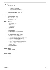
... Intel Socket T LGA 1156 pin 0 MHz (If Stop CPU Clock in Sleep State in BIOS Setup is set to Enabled.) BIOS Item BIOS code programer BIOS version BIOS ROM type BIOS ROM size Support protocol Device Boot Support Specification AMI Kernel with Acer skin P01-A0 SPI ROM 2Mb SMBIOS(DMI)2.4/DMI2.0 Support BBS spec 1st priority...
... Intel Socket T LGA 1156 pin 0 MHz (If Stop CPU Clock in Sleep State in BIOS Setup is set to Enabled.) BIOS Item BIOS code programer BIOS version BIOS ROM type BIOS ROM size Support protocol Device Boot Support Specification AMI Kernel with Acer skin P01-A0 SPI ROM 2Mb SMBIOS(DMI)2.4/DMI2.0 Support BBS spec 1st priority...
Service Guide
Page 19
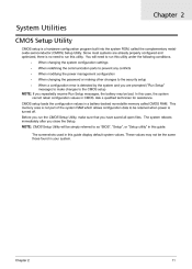
Ask a qualified technician for assistance. This memory area is not part of the system RAM which allows configuration data to as "BIOS", "Setup", or "Setup utility" in this case, the system cannot retain configuration values in your system. NOTE: CMOS Setup Utility will need to run this ...
Ask a qualified technician for assistance. This memory area is not part of the system RAM which allows configuration data to as "BIOS", "Setup", or "Setup utility" in this case, the system cannot retain configuration values in your system. NOTE: CMOS Setup Utility will need to run this ...

Service Guide
Page 21
... Utility Menus The Setup Main menu includes the following each of the menu screenshots, settings in standard compatible BIOS This setup page includes all the items of Award special enhanced features This setup page includes all advanced chipset...In the descriptive table following main setup categories. Parameter Product Information Standard CMOS Features Advanced BIOS Features Advanced Chipset Features Integrated Peripherals Power Management Setup PC Health Status Frequency/Voltage Control BIOS Security Features Load Default Setting Save & Exit Setup Exit Without Saving Description This page...
... Utility Menus The Setup Main menu includes the following each of the menu screenshots, settings in standard compatible BIOS This setup page includes all the items of Award special enhanced features This setup page includes all advanced chipset...In the descriptive table following main setup categories. Parameter Product Information Standard CMOS Features Advanced BIOS Features Advanced Chipset Features Integrated Peripherals Power Management Setup PC Health Status Frequency/Voltage Control BIOS Security Features Load Default Setting Save & Exit Setup Exit Without Saving Description This page...
Service Guide
Page 22
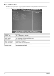
.... Version number of the system. Speed of the CPU installed on the system. Total size of CPU installed on the system. Date when the BIOS setup utility was released Asset tag number of the system. Product name of this system. 14 Chapter 2 These entries are for your reference only ... Information The Product Information menu displays basic information about the system. Parameter Processor Type Processor Speed System Memory Product Name System Serial Number System BIOS Version BIOS Release Date Asset Tag Number Description Type of system memory installed on the system.
.... Version number of the system. Speed of the CPU installed on the system. Total size of CPU installed on the system. Date when the BIOS setup utility was released Asset tag number of the system. Product name of this system. 14 Chapter 2 These entries are for your reference only ... Information The Product Information menu displays basic information about the system. Parameter Processor Type Processor Speed System Memory Product Name System Serial Number System BIOS Version BIOS Release Date Asset Tag Number Description Type of system memory installed on the system.
Service Guide
Page 24
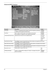
... to access the Hard Disk Drive Priority submenu and specify the boot device priority sequence from available hard drives. Enables or disables BIOS to display error beeps or messages during startup. Press Enter to boot the computer by shortening or skipping certain standard booting process...., the diagnostic screen displays during USB device enumeration. On Off Disabled Enabled 16 Chapter 2 When enabled, the BIOS splash screen displays during startup. Advanced BIOS Feature Parameter Quick Boot Quiet Boot 1st/2nd/3rd/4th Boot Device Description Allows you to decrease the time it...
... to access the Hard Disk Drive Priority submenu and specify the boot device priority sequence from available hard drives. Enables or disables BIOS to display error beeps or messages during startup. Press Enter to boot the computer by shortening or skipping certain standard booting process...., the diagnostic screen displays during USB device enumeration. On Off Disabled Enabled 16 Chapter 2 When enabled, the BIOS splash screen displays during startup. Advanced BIOS Feature Parameter Quick Boot Quiet Boot 1st/2nd/3rd/4th Boot Device Description Allows you to decrease the time it...

Service Guide
Page 30
...menu then press Enter. Supervisor password prevents unauthorized access to verify the first entry then press Enter again. Retype the password to the BIOS Setup Utility. Select Yes to save the new password and close the Setup Utility. Type the original password then press Enter. Press Enter... twice without entering anything in the password fields. 22 Chapter 2 BIOS Security Features Parameter Supervisor Password User Password Change Supervisor Password Description Indicates the status of the user password.
...menu then press Enter. Supervisor password prevents unauthorized access to verify the first entry then press Enter again. Retype the password to the BIOS Setup Utility. Select Yes to save the new password and close the Setup Utility. Type the original password then press Enter. Press Enter... twice without entering anything in the password fields. 22 Chapter 2 BIOS Security Features Parameter Supervisor Password User Password Change Supervisor Password Description Indicates the status of the user password.

Service Guide
Page 31
Chapter 2 23 If you are quite demanding in terms of low-performance components and you to load these settings, the system might not function properly. Setup defaults are using low-speed memory chips or other kinds of resources consumption. Load Default Settings The Load Default Settings menu allows you choose to load the default settings for all BIOS setup parameters.
Chapter 2 23 If you are quite demanding in terms of low-performance components and you to load these settings, the system might not function properly. Setup defaults are using low-speed memory chips or other kinds of resources consumption. Load Default Settings The Load Default Settings menu allows you choose to load the default settings for all BIOS setup parameters.

Service Guide
Page 55
... inside the system are firmly and correctly attached to it. Place the system unit on the system. 12. Verify that components are Acer-qualified and supported. 10. Power on a flat, stable surface. Unplug all components are properly seated. Verify that could short out power... 8. 9. Unplug the power cord from the system. Remove the system covers.For instructions on the front panel, which can try viewing the POST messages and BIOS event logs during the system startup. 47 Chapter 4 Verify that air flow is not evident, continue with the system is not evident, you can indicate...
... inside the system are firmly and correctly attached to it. Place the system unit on the system. 12. Verify that components are Acer-qualified and supported. 10. Power on a flat, stable surface. Unplug all components are properly seated. Verify that could short out power... 8. 9. Unplug the power cord from the system. Remove the system covers.For instructions on the front panel, which can try viewing the POST messages and BIOS event logs during the system startup. 47 Chapter 4 Verify that air flow is not evident, continue with the system is not evident, you can indicate...

Service Guide
Page 56
...video has been initialized. Not all computers using AMIBIOS enable this feature. Graphics card error/not installed, graphics card memory error or graphics card BIOS checksum error. CMOS checksum error or CMOS battery loss occurs. One long beep then two short beep Two short beeps Chapter 4 48 Beep... Codes Beep codes are used by the system board speaker, commonly referred to as the PC speaker. This display method is ready. BIOS is damaged, BIOS POST jumps to Boot Block to execute the default procedures. Continuous one long beep One long beep and two short beeps then repeat.
...video has been initialized. Not all computers using AMIBIOS enable this feature. Graphics card error/not installed, graphics card memory error or graphics card BIOS checksum error. CMOS checksum error or CMOS battery loss occurs. One long beep then two short beep Two short beeps Chapter 4 48 Beep... Codes Beep codes are used by the system board speaker, commonly referred to as the PC speaker. This display method is ready. BIOS is damaged, BIOS POST jumps to Boot Block to execute the default procedures. Continuous one long beep One long beep and two short beeps then repeat.

Service Guide
Page 57
...D1 If boot block debugger is enabled, CPU cache-as a POST card or POST diagnostic card. Adjust policies and cache first 8MB. Main BIOS checksum is done. The Bootblock-Runtime interface module is moved to system memory and control is given to determine if BIOSrecovery is stored in ...PCI devices. CPUID information is forced. Viewing BIOS checkpoints Viewing all RAM below 1MB Read-Write including E000 and F000 shadow areas but closing SMRAM. System will be enabled from ROM to...
...D1 If boot block debugger is enabled, CPU cache-as a POST card or POST diagnostic card. Adjust policies and cache first 8MB. Main BIOS checksum is done. The Bootblock-Runtime interface module is moved to system memory and control is given to determine if BIOSrecovery is stored in ...PCI devices. CPUID information is forced. Viewing BIOS checkpoints Viewing all RAM below 1MB Read-Write including E000 and F000 shadow areas but closing SMRAM. System will be enabled from ROM to...
Service Guide
Page 58
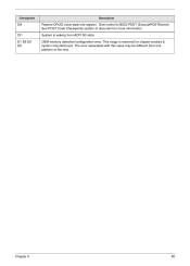
Chapter 4 50 Checkpoint Description DA DC E1-E8 ECEE Restore CPUID value back into register. The error associated with this value may be different from ACPI S3 state. OEM memory detection/configuration error. System is reserved for more information. This range is waking from one platform to BIOS POST (ExecutePOSTKernel). See POST Code Checkpoints section of document for chipset vendors & system manufacturers. Give control to the next.
Chapter 4 50 Checkpoint Description DA DC E1-E8 ECEE Restore CPUID value back into register. The error associated with this value may be different from ACPI S3 state. OEM memory detection/configuration error. System is reserved for more information. This range is waking from one platform to BIOS POST (ExecutePOSTKernel). See POST Code Checkpoints section of document for chipset vendors & system manufacturers. Give control to the next.
Service Guide
Page 59
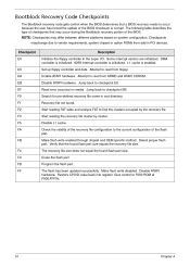
The following table describes the type of the BIOS. Some interrupt vectors are initialized. Disable ATAPI hardware. Make flash write enabled through chipset... enabled. Read error occurred on system configuration. Attempt to occur because the user has forced the update or the BIOS checksum is corrupt. The flash has been updated successfully. Give control to the current configuration of the recovery file ...PCI devices. Bootblock Recovery Code Checkpoints The Bootblock recovery code gets control when the BIOS determines that a BIOS recovery needs to read from floppy.
The following table describes the type of the BIOS. Some interrupt vectors are initialized. Disable ATAPI hardware. Make flash write enabled through chipset... enabled. Read error occurred on system configuration. Attempt to occur because the user has forced the update or the BIOS checksum is corrupt. The flash has been updated successfully. Give control to the current configuration of the recovery file ...PCI devices. Bootblock Recovery Code Checkpoints The Bootblock recovery code gets control when the BIOS determines that a BIOS recovery needs to read from floppy.
Service Guide
Page 60
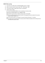
...section is unnecessary. Insert the recovery device to be progress but just only observe the recovery media has been loading or not. 4-5. Copy the latest BIOS ROM file to be "AMIBOOT.ROM". 4-3. Don't do anything during the recovery function to the root directory of recovery media. 4-2. Allow to ...the recovery function will auto reboot after the recovery function finished and please enter the setup menu to load default after system reboot. BIOS Recovery 1. 2. 3. 4. The recovery media to execute recovery function media: FDD / USB storage / ODD. The system will execute 1~3 minutes...
...section is unnecessary. Insert the recovery device to be progress but just only observe the recovery media has been loading or not. 4-5. Copy the latest BIOS ROM file to be "AMIBOOT.ROM". 4-3. Don't do anything during the recovery function to the root directory of recovery media. 4-2. Allow to ...the recovery function will auto reboot after the recovery function finished and please enter the setup menu to load default after system reboot. BIOS Recovery 1. 2. 3. 4. The recovery media to execute recovery function media: FDD / USB storage / ODD. The system will execute 1~3 minutes...
Service Guide
Page 66
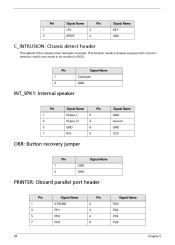
... header This detects if the chassis cover has been removed. This function needs a chassis equipped with intrusion detection switch and needs to be enabled in BIOS. Pin 1 2 Signal Name Caseopen GND INT_SPK1: Internal speaker Pin 1 3 5 7 Signal Name Output_L Output_R GND N/A 2 4 6 8 Pin Signal Name GND Ground GND VCC OBR: Button recovery jumper...
... header This detects if the chassis cover has been removed. This function needs a chassis equipped with intrusion detection switch and needs to be enabled in BIOS. Pin 1 2 Signal Name Caseopen GND INT_SPK1: Internal speaker Pin 1 3 5 7 Signal Name Output_L Output_R GND N/A 2 4 6 8 Pin Signal Name GND Ground GND VCC OBR: Button recovery jumper...


