Service Guide
Page 74
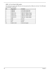
The USB header pins description is as follows: Pin Signal Name 1 USBPWR 2 USBPWR 3 USB_FP_P0- 4 USB_FP_P1- 5 USB_FP_P0+ 6 USB_FP_P1+ 7 GND 8 GND 9 Key 10 USB_FP_OC0 Function Front Panel USB Power Front Panel USB Power USB Port 0 Negative Signal USB Port 1 Negative Signal USB Port 0 Positive Signal USB Port 1 Positive Signal Ground Ground No pin Overcurrent signal 66 Chapter 5 USBF1~4: Front Panel USB headers The motherboard supports eight USB ports on the rear panel and four USB ports on the front.
The USB header pins description is as follows: Pin Signal Name 1 USBPWR 2 USBPWR 3 USB_FP_P0- 4 USB_FP_P1- 5 USB_FP_P0+ 6 USB_FP_P1+ 7 GND 8 GND 9 Key 10 USB_FP_OC0 Function Front Panel USB Power Front Panel USB Power USB Port 0 Negative Signal USB Port 1 Negative Signal USB Port 0 Positive Signal USB Port 1 Positive Signal Ground Ground No pin Overcurrent signal 66 Chapter 5 USBF1~4: Front Panel USB headers The motherboard supports eight USB ports on the rear panel and four USB ports on the front.
Service Guide
Page 75
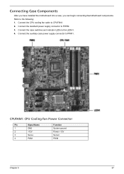
Connect the auxiliary case power supply connector to the following: 1. Connecting Case Components After you have installed the motherboard into a case, you can begin connecting themotherboard components. Refer to PWR1. CPUFAN1: CPU Cooling Fan Power Connector Pin Signal Name 1 GND 2 +12V 3 Sense 4 PWM Function System ground Power +12V Sensor PWM Chapter 5 67 Connect the standard power supply connector to the LEDH1. 4. Connect the case switches and indicator LEDs to PWR2. 3. Connect the CPU cooling fan cable to CPUFAN1. 2.
Connect the auxiliary case power supply connector to the following: 1. Connecting Case Components After you have installed the motherboard into a case, you can begin connecting themotherboard components. Refer to PWR1. CPUFAN1: CPU Cooling Fan Power Connector Pin Signal Name 1 GND 2 +12V 3 Sense 4 PWM Function System ground Power +12V Sensor PWM Chapter 5 67 Connect the standard power supply connector to the LEDH1. 4. Connect the case switches and indicator LEDs to PWR2. 3. Connect the CPU cooling fan cable to CPUFAN1. 2.


