
Acer Aspire M3470 Service Guide
Page 7
... 30 Removing the TV-Tuner Card 32 Removing the VGA Card 34 Removing the Hard Disk Drive 35 Removing the Optical Drive 37 Removing the Power Supply 39 Removing the System Fan 41 Removing the Memory Modules 42 Removing the Mainboard 43 Removing the Top Cover 46 Removing the... 55 Install the Memory 57 Romoving the Side Panel 58 Removing the Cage of Hard Disk Drive 59 Removing the PCI Cover 60 Install the Power Supply 61 Install the I/O Shielding 62 Install the Main Board 63 Install the System Fan 65 Install the Optical Drive 66 Install the Hard Disk Drive...
... 30 Removing the TV-Tuner Card 32 Removing the VGA Card 34 Removing the Hard Disk Drive 35 Removing the Optical Drive 37 Removing the Power Supply 39 Removing the System Fan 41 Removing the Memory Modules 42 Removing the Mainboard 43 Removing the Top Cover 46 Removing the... 55 Install the Memory 57 Romoving the Side Panel 58 Removing the Cage of Hard Disk Drive 59 Removing the PCI Cover 60 Install the Power Supply 61 Install the I/O Shielding 62 Install the Main Board 63 Install the System Fan 65 Install the Optical Drive 66 Install the Hard Disk Drive...
Acer Aspire M3470 Service Guide
Page 11
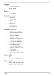
...* RJ45 • 4*USB2.0 ports • 2 * USB3.0 ports • 1 * 3 ports Audio jack On-board connectors • 1 * 24-pin ATX PWR connector • 1 * H2X2 Power Supply Connector • 3 * SATA 6Gb/s for A75 • 3 * USB2.0 H5X2 Header • 1 * USB3.0 2*10 Header • 1 * Front Audio Pannel H5X2 header • 1 * Front... 2 * H1X2 GPIO header • 1 * 3pin IR receiver header to super I/O System BIOS • 2Mb • AMI Kernel with Acer skin/copyright Power supply • Non PFC 250W / PFC 250W /FR 300W. • Support models are listed on board buzzer. Chapter 1 3
...* RJ45 • 4*USB2.0 ports • 2 * USB3.0 ports • 1 * 3 ports Audio jack On-board connectors • 1 * 24-pin ATX PWR connector • 1 * H2X2 Power Supply Connector • 3 * SATA 6Gb/s for A75 • 3 * USB2.0 H5X2 Header • 1 * USB3.0 2*10 Header • 1 * Front Audio Pannel H5X2 header • 1 * Front... 2 * H1X2 GPIO header • 1 * 3pin IR receiver header to super I/O System BIOS • 2Mb • AMI Kernel with Acer skin/copyright Power supply • Non PFC 250W / PFC 250W /FR 300W. • Support models are listed on board buzzer. Chapter 1 3
Acer Aspire M3470 Service Guide
Page 28
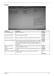
.... Enables or disables the system to dowake-up the system by USB KB/ Mouse Restore On AC Power Loss Description Select an ACPI state. Power Parameter ACPI Suspend Mode Deep Power Off Mode Power On by RTC Alarm Power On by PCIE Devices Wake Up by PS/2 KB/ Mouse Wake Up by RTC Alarm Function... This system can automatically resume if there is an incoming call on the PCIE LAN card.You must use an ATX power supply in order to use this feature.Use this item, the system can be turned off Mode Enables or Disables to wake up the system from...
.... Enables or disables the system to dowake-up the system by USB KB/ Mouse Restore On AC Power Loss Description Select an ACPI state. Power Parameter ACPI Suspend Mode Deep Power Off Mode Power On by RTC Alarm Power On by PCIE Devices Wake Up by PS/2 KB/ Mouse Wake Up by RTC Alarm Function... This system can automatically resume if there is an incoming call on the PCIE LAN card.You must use an ATX power supply in order to use this feature.Use this item, the system can be turned off Mode Enables or Disables to wake up the system from...

Acer Aspire M3470 Service Guide
Page 37
Remove the heat sink fan assembly from the chassis then lay it down the heat sink fan assembly, in an upright position-with the thermal patch facing upward. 3. Lift the heat sink fan assembly away from both the heat sink and the processor. 29 Chapter 3 Do not let the thermal patch on top of the power supply, as shown below, then disconnect the fan cable from the mainboard. 5. Use an alcohol pad to wipe off the thermal grease from the mainboard. 4. Lay down in an upright position, on the heat sink fan assembly touch the work surface. 6.
Remove the heat sink fan assembly from the chassis then lay it down the heat sink fan assembly, in an upright position-with the thermal patch facing upward. 3. Lift the heat sink fan assembly away from both the heat sink and the processor. 29 Chapter 3 Do not let the thermal patch on top of the power supply, as shown below, then disconnect the fan cable from the mainboard. 5. Use an alcohol pad to wipe off the thermal grease from the mainboard. 4. Lay down in an upright position, on the heat sink fan assembly touch the work surface. 6.

Acer Aspire M3470 Service Guide
Page 47
Removing the Power Supply 1. Disconnect the 4-pin and 24-pin power supply cables from the mainboard. 39 Chapter 3 Use a knife to cut the cable tying. 2.
Removing the Power Supply 1. Disconnect the 4-pin and 24-pin power supply cables from the mainboard. 39 Chapter 3 Use a knife to cut the cable tying. 2.
Acer Aspire M3470 Service Guide
Page 48
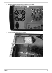
3. Lift the power supply module out of the chassis. Remove the four screws that secures the power supply to the chassis. 4. Chapter 3 40
3. Lift the power supply module out of the chassis. Remove the four screws that secures the power supply to the chassis. 4. Chapter 3 40

Acer Aspire M3470 Service Guide
Page 69
Install the power supply to chassis. 2. Install the Power Supply 1. Fix the four screws. 61 Chapter 3
Install the power supply to chassis. 2. Install the Power Supply 1. Fix the four screws. 61 Chapter 3

Acer Aspire M3470 Service Guide
Page 102
ITEM 1 2 3 4 5 6 7 8 9 10 11 12 13 14 15 16 17 18 19 20 NAME PCI Door Rear Chassis IO Shielding Power Supply MB Chassis Support Chassis Support MB Support Sub Chassis Holder Bezel Top Bezel Cover Deco Power Button Spring Switch HDD Lens LED MCR Top USB ODD Button Up Q'TY 1 1 1 1 1 1 1 1 1 1 1 1 1 1 1 1 1 1 1 1 ITEM 21 22 23... 24 25 26 27 28 29 30 31 32 33 34 35 36 37 38 39 NAME ODD Button Dn Pole ODD Door Up ODD Door Dn Deco Bezel Acer Logo Hinge...
ITEM 1 2 3 4 5 6 7 8 9 10 11 12 13 14 15 16 17 18 19 20 NAME PCI Door Rear Chassis IO Shielding Power Supply MB Chassis Support Chassis Support MB Support Sub Chassis Holder Bezel Top Bezel Cover Deco Power Button Spring Switch HDD Lens LED MCR Top USB ODD Button Up Q'TY 1 1 1 1 1 1 1 1 1 1 1 1 1 1 1 1 1 1 1 1 ITEM 21 22 23... 24 25 26 27 28 29 30 31 32 33 34 35 36 37 38 39 NAME ODD Button Dn Pole ODD Door Up ODD Door Dn Deco Bezel Acer Logo Hinge...

Acer Aspire M3470 Service Guide
Page 107
Category Power Supply Mouse Keyboard 99 Part Number Acer P/N Philips OVU710018 Win7 receiver Philips code for EMEA, H57 fixed FW, pair with acer logo MS.11200.104 Keyboard LITE-ON SK-9660B RF2.4 Black US KB.RF40B.167 N/A Chapter 6 module PSU DELTA DPS-300AB-57A 300W Active PFC ... battery MS.11200.122 Lite-on mouse USB SM-9020B black;with new acer logo MS.11200.123 Primax mouse RF2.4 MORFF9UO black color;with new acer logo MS.11200.113 Primax mouse RF2.4 MORFF9UO black color;with new acer logo;without battery MS.11200.114 Primax mouse USB MOF9UO black color;with...
Category Power Supply Mouse Keyboard 99 Part Number Acer P/N Philips OVU710018 Win7 receiver Philips code for EMEA, H57 fixed FW, pair with acer logo MS.11200.104 Keyboard LITE-ON SK-9660B RF2.4 Black US KB.RF40B.167 N/A Chapter 6 module PSU DELTA DPS-300AB-57A 300W Active PFC ... battery MS.11200.122 Lite-on mouse USB SM-9020B black;with new acer logo MS.11200.123 Primax mouse RF2.4 MORFF9UO black color;with new acer logo MS.11200.113 Primax mouse RF2.4 MORFF9UO black color;with new acer logo;without battery MS.11200.114 Primax mouse USB MOF9UO black color;with...


