
Acer Aspire M3450 Desktop Service Guide
Page 7
... 27 Removing the Heat Sink Fan Assembly 28 Removing the Processor 30 Removing the VGA Card 32 Removing the TV-Tuner Card 34 Removing the PCI-E Modem Card 35 Removing the Wireless Lan Card 36 Removing the Memory Modules 37 Removing the Hard Disk Drive 38 Removing the Optical Drive 40 Removing the System Fan 42 Removing the Daughter Board 44 Removing the Power Supply 45 Removing the Mainboard 46 Removing the Top Cover 49 Removing the Power Switch and LED Cable Assembly 51 Removing the Card Reader 52 Removing the Top USB and Audio I/O Assembly...
... 27 Removing the Heat Sink Fan Assembly 28 Removing the Processor 30 Removing the VGA Card 32 Removing the TV-Tuner Card 34 Removing the PCI-E Modem Card 35 Removing the Wireless Lan Card 36 Removing the Memory Modules 37 Removing the Hard Disk Drive 38 Removing the Optical Drive 40 Removing the System Fan 42 Removing the Daughter Board 44 Removing the Power Supply 45 Removing the Mainboard 46 Removing the Top Cover 49 Removing the Power Switch and LED Cable Assembly 51 Removing the Card Reader 52 Removing the Top USB and Audio I/O Assembly...
Acer Aspire M3450 Desktop Service Guide
Page 8
... Wireless LAN Card 76 Install the PCI-E Modem Card 77 Install the TV-Tuner Card 78 Install the VGA Card 79 Install the Front Bezel 80 Install the Side Panel 81 System Troubleshooting 82 Hardware Diagnostic Procedure 82 System Check Procedures 83 Power System Check 83 System External Inspection 83 System Internal Inspection 83 Beep Codes 84 Checkpoints 85 BIOS Recovery 88 Jumper and Connector Information 89 M/B Placement 89 Jumper Setting 91 Setting Jumper 91 FRU (Field Replaceable Unit) List 98 Aspire M3450 Exploded Diagram...
... Wireless LAN Card 76 Install the PCI-E Modem Card 77 Install the TV-Tuner Card 78 Install the VGA Card 79 Install the Front Bezel 80 Install the Side Panel 81 System Troubleshooting 82 Hardware Diagnostic Procedure 82 System Check Procedures 83 Power System Check 83 System External Inspection 83 System Internal Inspection 83 Beep Codes 84 Checkpoints 85 BIOS Recovery 88 Jumper and Connector Information 89 M/B Placement 89 Jumper Setting 91 Setting Jumper 91 FRU (Field Replaceable Unit) List 98 Aspire M3450 Exploded Diagram...
Acer Aspire M3450 Desktop Service Guide
Page 9
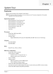
... BIOS specification. Chipset • NB: AMD RS880P. • SB: AMD SB950. PCB • MicroATX Size, 244mm x 244mm Memory subsystem • Socket Type: DDR III connector. • Socket Quantity: 4 DIMMs. • Channel A: Slot 2, 4; memory module. • Should meet AMD chipset platform design guide. • Dual channel should be enabled always when plug-in this section is for slot 1/2 and slot 3/4. • Speed: 1333MHz. • Capacity support...
... BIOS specification. Chipset • NB: AMD RS880P. • SB: AMD SB950. PCB • MicroATX Size, 244mm x 244mm Memory subsystem • Socket Type: DDR III connector. • Socket Quantity: 4 DIMMs. • Channel A: Slot 2, 4; memory module. • Should meet AMD chipset platform design guide. • Dual channel should be enabled always when plug-in this section is for slot 1/2 and slot 3/4. • Speed: 1333MHz. • Capacity support...
Acer Aspire M3450 Desktop Service Guide
Page 10
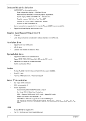
... HDMI CTS 1.4 compliance. • Need to measure VGA follow Acer VGA SOP. • Support for Cool 'n' Quiet™ via FID/VID change. • Support for internal SATA port. • CD-ROME/CD-RW/DVD-ROM/DVD-RW/DVD+RW/DVD Dual/DVD SuperMultiPlus/ Blu-Ray ODD. LAN • • Realtek 8111E VL Gigabit LAN. Port: 1 x RJ45 rear port from CPU side. Hard disk drive • Support up to four SATA ports • 3.5",25.4mm • Capacity and models are listed on AVLC Audio...
... HDMI CTS 1.4 compliance. • Need to measure VGA follow Acer VGA SOP. • Support for Cool 'n' Quiet™ via FID/VID change. • Support for internal SATA port. • CD-ROME/CD-RW/DVD-ROM/DVD-RW/DVD+RW/DVD Dual/DVD SuperMultiPlus/ Blu-Ray ODD. LAN • • Realtek 8111E VL Gigabit LAN. Port: 1 x RJ45 rear port from CPU side. Hard disk drive • Support up to four SATA ports • 3.5",25.4mm • Capacity and models are listed on AVLC Audio...

Acer Aspire M3450 Desktop Service Guide
Page 11
... 2.0/1.1 USB 3.0 • Controller: Etron EJ168A USB 3.0 • Rear IO: 2 ports. On-board connectors • 1 * AM3+ CPU socket. • 4 * DDR3 memory sockets. • 1 * PCI Express x16 slot. • 2 * PCI Express x1 slots. • 1 * PCI slot. • 1 * 24-pin ATX Power Supply connector. • 1 * 4-pin ATX Power Supply connector. • 1 * 3-pin CPU_FAN connector. • 1 * 3-pin SYS_FAN connector • 4 * USB 2.0 headers support additional 8 USB 2.0 ports. • 6 * Serial ATA 6Gb/s connectors. • 1 * Front panel switch/LED header. • 1 * Front panel audio...
... 2.0/1.1 USB 3.0 • Controller: Etron EJ168A USB 3.0 • Rear IO: 2 ports. On-board connectors • 1 * AM3+ CPU socket. • 4 * DDR3 memory sockets. • 1 * PCI Express x16 slot. • 2 * PCI Express x1 slots. • 1 * PCI slot. • 1 * 24-pin ATX Power Supply connector. • 1 * 4-pin ATX Power Supply connector. • 1 * 3-pin CPU_FAN connector. • 1 * 3-pin SYS_FAN connector • 4 * USB 2.0 headers support additional 8 USB 2.0 ports. • 6 * Serial ATA 6Gb/s connectors. • 1 * Front panel switch/LED header. • 1 * Front panel audio...
Acer Aspire M3450 Desktop Service Guide
Page 12
Power supply • 300W/500W(Support models are listed on AVLC). 4 Chapter 1 System BIOS • AMI BIOS with 32Mb SPI Flash ROM. • AMI Kernel with Acer skin/copyright. • Supports Multi-language BIOS Utility.
Power supply • 300W/500W(Support models are listed on AVLC). 4 Chapter 1 System BIOS • AMI BIOS with 32Mb SPI Flash ROM. • AMI Kernel with Acer skin/copyright. • Supports Multi-language BIOS Utility.
Acer Aspire M3450 Desktop Service Guide
Page 16
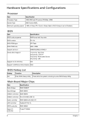
... VL SATA controller AMD SB950 Super IO controller Fintek F71869A 8 Chapter 1 Hardware Specifications and Configurations Processor Item Specification Processor Type AMD AM3 and FX series CPU(Max: 95W) Socket Type AMD Socket AM3+ Minimum operating speed 0 MHz (If Stop CPU Clock in Sleep State in BIOS Setup is set to Enabled.) BIOS Item Specification BIOS code programer AMI Kernel with Acer skin BIOS version P01-A1 BIOS ROM type SPI Flash BIOS ROM size 4Mb or 8Mb Support protocol SMBIOS(DMI)2.4/DMI2.0 Device Boot Support 1st priority: Hard Disk...
... VL SATA controller AMD SB950 Super IO controller Fintek F71869A 8 Chapter 1 Hardware Specifications and Configurations Processor Item Specification Processor Type AMD AM3 and FX series CPU(Max: 95W) Socket Type AMD Socket AM3+ Minimum operating speed 0 MHz (If Stop CPU Clock in Sleep State in BIOS Setup is set to Enabled.) BIOS Item Specification BIOS code programer AMI Kernel with Acer skin BIOS version P01-A1 BIOS ROM type SPI Flash BIOS ROM size 4Mb or 8Mb Support protocol SMBIOS(DMI)2.4/DMI2.0 Device Boot Support 1st priority: Hard Disk...

Acer Aspire M3450 Desktop Service Guide
Page 17
Audio Interface Item Audio controller Audio controller type Audio channel Audio function control Mono or stereo Compatibility Music synthesizer Sampling rate Microphone/Headphone jack Specification AMD SB950 ALC662-VC 5.1 channel Enable/disable by BIOS Setup Stereo It should defined by system level HW not support , it should be S/W app playback(DAC) 192K Supported Chapter 1 9 Memory Combinations Slot Memory Total Memory Slot 1 1MB,2GB,4GB 1G ~4GB Slot 2 1MB,2GB,4GB 1G ~4GB Slot 3 1MB...
Audio Interface Item Audio controller Audio controller type Audio channel Audio function control Mono or stereo Compatibility Music synthesizer Sampling rate Microphone/Headphone jack Specification AMD SB950 ALC662-VC 5.1 channel Enable/disable by BIOS Setup Stereo It should defined by system level HW not support , it should be S/W app playback(DAC) 192K Supported Chapter 1 9 Memory Combinations Slot Memory Total Memory Slot 1 1MB,2GB,4GB 1G ~4GB Slot 2 1MB,2GB,4GB 1G ~4GB Slot 3 1MB...
Acer Aspire M3450 Desktop Service Guide
Page 18
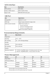
USB3.0 Ports Quantity: 2(Rear IO). S5 V N/A Disabled Disabled Disabled 10 Chapter 1 SATA Interface Item SATA controller Number of SATA channel Support mode Specification AMD SB950 SATA X 6(SATA 6Gb/s) RAID/AHCI/IDE mode option USB Port Item Universal HCI USB Class USB Connectors Quantity Specification USB 2.0/1.1 or 3.0 Support legacy keyboard for legacy mode USB2.0 Ports Quantity: 12 • 6 port for rear ports. • 4 ports for front daughter board. • 2 ports for rear daughter board. Environmental Requirements Item Specification Temperature Operating +5°C ~...
USB3.0 Ports Quantity: 2(Rear IO). S5 V N/A Disabled Disabled Disabled 10 Chapter 1 SATA Interface Item SATA controller Number of SATA channel Support mode Specification AMD SB950 SATA X 6(SATA 6Gb/s) RAID/AHCI/IDE mode option USB Port Item Universal HCI USB Class USB Connectors Quantity Specification USB 2.0/1.1 or 3.0 Support legacy keyboard for legacy mode USB2.0 Ports Quantity: 12 • 6 port for rear ports. • 4 ports for front daughter board. • 2 ports for rear daughter board. Environmental Requirements Item Specification Temperature Operating +5°C ~...
Acer Aspire M3450 Desktop Service Guide
Page 19
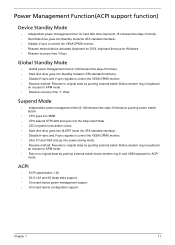
... in,keyboard an mouse for APM mode. • Resume recovery time :7-10sec Suspend Mode • Independent power management timer(2-120minutes,time step=10minute)or pushing extern switch button. • CPU goes into SMM • CPU asserts STPCLK# and goes into the Stop Grant State. • LED on panel turns amber colour. • Hard disk drive goes into SLEEP mode (for ATA standard interface). • Disable H-sync and V-sync signals to control the...
... in,keyboard an mouse for APM mode. • Resume recovery time :7-10sec Suspend Mode • Independent power management timer(2-120minutes,time step=10minute)or pushing extern switch button. • CPU goes into SMM • CPU asserts STPCLK# and goes into the Stop Grant State. • LED on panel turns amber colour. • Hard disk drive goes into SLEEP mode (for ATA standard interface). • Disable H-sync and V-sync signals to control the...

Acer Aspire M3450 Desktop Service Guide
Page 20
... a hardware configuration program built into the system ROM, called CMOS RAM. Chapter 2 System Utilities CMOS Setup Utility CMOS setup is turned off. Ask a qualified technician for assistance. NOTE: CMOS Setup Utility will need to run this utility under the following conditions. • When changing the system configuration settings • When redefining the communication ports to prevent any conflicts • When modifying the power management configuration • When changing the password or making other changes to the security setup • When a configuration error...
... a hardware configuration program built into the system ROM, called CMOS RAM. Chapter 2 System Utilities CMOS Setup Utility CMOS setup is turned off. Ask a qualified technician for assistance. NOTE: CMOS Setup Utility will need to run this utility under the following conditions. • When changing the system configuration settings • When redefining the communication ports to prevent any conflicts • When modifying the power management configuration • When changing the password or making other changes to the security setup • When a configuration error...
Acer Aspire M3450 Desktop Service Guide
Page 22
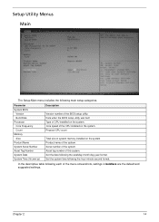
... BIOS setup utility. Set the system time following the weekday-month-day-year format. Core speed of the system. Chapter 2 14 Product name of the CPU installed on the system. Asset tag number of this system. In the descriptive table following main setup categories. Setup Utility Menus Main The Setup Main menu includes the following each of the menu screenshots, settings in boldface are the default...
... BIOS setup utility. Set the system time following the weekday-month-day-year format. Core speed of the system. Chapter 2 14 Product name of the CPU installed on the system. Asset tag number of this system. In the descriptive table following main setup categories. Setup Utility Menus Main The Setup Main menu includes the following each of the menu screenshots, settings in boldface are the default...
Acer Aspire M3450 Desktop Service Guide
Page 30
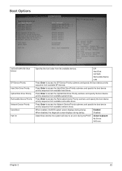
...the boot device priority sequence from available network drives. Boot Options 1st/2nd/3rd/4th/5th Boot Device EFI Device Priority Hard Disk Drive Priority Optical Disk Drive Priority Removable Device Priority Network Device Priority Quiet Boot Halt On Specifies the boot order from available EFI devices. EFI Hard Disk CD^DVD Removable Device LAN Press Enter to access the EFI Device Priority submenu and specify the boot device priority sequence from the available devices. All,but keyboard No Errors All Errors Chapter 2 22 When disabled, the diagnostic screen displays during startup...
...the boot device priority sequence from available network drives. Boot Options 1st/2nd/3rd/4th/5th Boot Device EFI Device Priority Hard Disk Drive Priority Optical Disk Drive Priority Removable Device Priority Network Device Priority Quiet Boot Halt On Specifies the boot order from available EFI devices. EFI Hard Disk CD^DVD Removable Device LAN Press Enter to access the EFI Device Priority submenu and specify the boot device priority sequence from the available devices. All,but keyboard No Errors All Errors Chapter 2 22 When disabled, the diagnostic screen displays during startup...
Acer Aspire M3450 Desktop Service Guide
Page 90
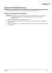
... to recreate the failure by running the diagnostic tests or repeating thesame operation. 3. Refer to "Power System check" on page 83 and "Beep Codes" on how to troubleshoot system hardware problems. Hardware Diagnostic Procedure IMPORTANT:The diagnostic tests described in as much detail as possible. 2. Chapter 4 82 NonAcerproducts, prototype cards, or modified options can give false errors and invalid systemresponses. 1. Chapter 4 System Troubleshooting This chapter provides instructions on page 84...
... to recreate the failure by running the diagnostic tests or repeating thesame operation. 3. Refer to "Power System check" on page 83 and "Beep Codes" on how to troubleshoot system hardware problems. Hardware Diagnostic Procedure IMPORTANT:The diagnostic tests described in as much detail as possible. 2. Chapter 4 82 NonAcerproducts, prototype cards, or modified options can give false errors and invalid systemresponses. 1. Chapter 4 System Troubleshooting This chapter provides instructions on page 84...

Acer Aspire M3450 Desktop Service Guide
Page 93
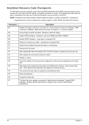
... faster access. This display method islimited, since it only displays checkpoints thatoccur after the video card has been activated. NMI is available. If memory sizing module not executed, start memory refresh and do memory sizing in PMM. Copies compressed boot block code to as -RAM functionality is enabled. Go to execute serial flash. Leaves all checkpoints generated by the BIOS requires acheckpoint card, also referred to memory in PCI devices...
... faster access. This display method islimited, since it only displays checkpoints thatoccur after the video card has been activated. NMI is available. If memory sizing module not executed, start memory refresh and do memory sizing in PMM. Copies compressed boot block code to as -RAM functionality is enabled. Go to execute serial flash. Leaves all checkpoints generated by the BIOS requires acheckpoint card, also referred to memory in PCI devices...
Acer Aspire M3450 Desktop Service Guide
Page 95
... from add-in PCI devices. Jump back to the current configuration of the BIOS. Disable L1 cache. Make flash write enabled through chipset and OEM specific method. DMA controller is initialized. 8259 interrupt controller is corrupt. Restore CPUID value back into register. Give control to checkpoint EB. Enable ATAPI hardware. The flash has been updated successfully. Jump back to F000 ROM at F000:FFF0h. 87 Chapter 4 Start reading the recovery file...
... from add-in PCI devices. Jump back to the current configuration of the BIOS. Disable L1 cache. Make flash write enabled through chipset and OEM specific method. DMA controller is initialized. 8259 interrupt controller is corrupt. Restore CPUID value back into register. Give control to checkpoint EB. Enable ATAPI hardware. The flash has been updated successfully. Jump back to F000 ROM at F000:FFF0h. 87 Chapter 4 Start reading the recovery file...
Acer Aspire M3450 Desktop Service Guide
Page 96
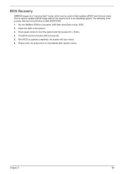
... and then press Ctrl + Home. 4. The following is used to flash update a BIOS from the boot block. After BIOS is updated completely, the system will be used to update a BIOS image without the need to boot to flash BIOS ROM. 1. This is the process that user should follow to an operating system. Chapter 4 88 The BIOS recovery function will auto reboot. 6. Press power button to a bootable USB flash drive(Disk on Key, DOK). 2. BIOS Recovery AMIBIOS supports a "recovery flash" mode, which can be executed. 5.
... and then press Ctrl + Home. 4. The following is used to flash update a BIOS from the boot block. After BIOS is updated completely, the system will be used to update a BIOS image without the need to boot to flash BIOS ROM. 1. This is the process that user should follow to an operating system. Chapter 4 88 The BIOS recovery function will auto reboot. 6. Press power button to a bootable USB flash drive(Disk on Key, DOK). 2. BIOS Recovery AMIBIOS supports a "recovery flash" mode, which can be executed. 5.

Acer Aspire M3450 Desktop Service Guide
Page 98
... 1 CPU Socket 2 CPU_FAN 3 DDR3_1~4 4 ATX_POWER 5 SATA1~6 6 F_PANEL 7 F_USB1~4 8 F_AUDIO 9 PCI 10 CLR_CMOS 11 PCIE1X-1~2 12 PCIE16X 13 SYS_FAN 14 ATX_12V Description Supports AMD AM3/AM3+ CPUs 4-pin CPU cooling fan connector 240-pin DDR3 SDRAM slots Standard 24-pin ATX power connector Serial ATA 6.0 Gb/s connectors Front panel switch/LED header Front panel USB 2.0 header Front panel audio header 32-bit add-on card slot Clear CMOS jumper PCI Express x1 slots PCI Express slot for graphics interface 3-pin system cooling fan connector 4-pin +12V power connector 90...
... 1 CPU Socket 2 CPU_FAN 3 DDR3_1~4 4 ATX_POWER 5 SATA1~6 6 F_PANEL 7 F_USB1~4 8 F_AUDIO 9 PCI 10 CLR_CMOS 11 PCIE1X-1~2 12 PCIE16X 13 SYS_FAN 14 ATX_12V Description Supports AMD AM3/AM3+ CPUs 4-pin CPU cooling fan connector 240-pin DDR3 SDRAM slots Standard 24-pin ATX power connector Serial ATA 6.0 Gb/s connectors Front panel switch/LED header Front panel USB 2.0 header Front panel audio header 32-bit add-on card slot Clear CMOS jumper PCI Express x1 slots PCI Express slot for graphics interface 3-pin system cooling fan connector 4-pin +12V power connector 90...
Acer Aspire M3450 Desktop Service Guide
Page 99
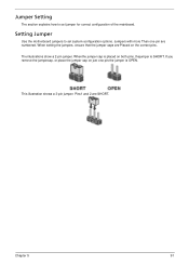
.... When setting the jumpers, ensure that the jumper caps are SHORT. Chapter 5 91 Pins1 and 2 are Placed on the correct pins. Setting Jumper Use the motherboard jumpers to set system configuration options. Whenthe jumper cap is placed on just one pin are numbered. The illustrations show a 2-pin jumper. Jumpers with more Than one pin,the jumper is SHORT. If you remove the jumpercap, or place the jumper cap on both pins, thejumper is OPEN.
.... When setting the jumpers, ensure that the jumper caps are SHORT. Chapter 5 91 Pins1 and 2 are Placed on the correct pins. Setting Jumper Use the motherboard jumpers to set system configuration options. Whenthe jumper cap is placed on just one pin are numbered. The illustrations show a 2-pin jumper. Jumpers with more Than one pin,the jumper is SHORT. If you remove the jumpercap, or place the jumper cap on both pins, thejumper is OPEN.
Acer Aspire M3450 Desktop Service Guide
Page 103
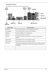
.... The third jack is for microphone. Use the USB 3.0 ports to connect audio devices. Use the lower PS/2 port to the HDMI device. Connect an RJ-45 jack to the LAN port to connect your monitor to the VGA port. Connect the HDMI port to connect a PS/2 keyboard. Chapter 5 95 Connecting I/O Devices The backplane of the motherboard has the following I/O ports: I/O Port Name PS2 Mouse PS2 Keyboard HDMI Port VGA Port LAN Port USB 2.0 Ports USB 3.0 Ports Audio Ports I/O Port Function Use the upper PS/2 port to connect USB 2.0 devices. Use the USB 2.0 ports to connect a PS/2 pointing...
.... The third jack is for microphone. Use the USB 3.0 ports to connect audio devices. Use the lower PS/2 port to the HDMI device. Connect an RJ-45 jack to the LAN port to connect your monitor to the VGA port. Connect the HDMI port to connect a PS/2 keyboard. Chapter 5 95 Connecting I/O Devices The backplane of the motherboard has the following I/O ports: I/O Port Name PS2 Mouse PS2 Keyboard HDMI Port VGA Port LAN Port USB 2.0 Ports USB 3.0 Ports Audio Ports I/O Port Function Use the upper PS/2 port to connect USB 2.0 devices. Use the USB 2.0 ports to connect a PS/2 pointing...


