Acer Aspire M3420 Desktop Service Guide
Page 8
Reinstalling the Heat Sink Fan Assembly 85 Reinstalling the Front Bezel 87 Reinstalling the Side Panel 89 System Troubleshooting 90 Hardware Diagnostic Procedure 90 System Check Procedures 91 Power System Check 91 System External Inspection 91 System Internal Inspection 91 Beep Codes 92 Checkpoints 93 BIOS Recovery 96 Jumper and Connector Information 99 M/B Placement 99 Jumper Setting 101 Setting Jumper 101 FRU (Field Replaceable Unit) List 110 Aspire M3420 Exploded Diagram 111 Aspire M3420 FRU List 113 viii
Reinstalling the Heat Sink Fan Assembly 85 Reinstalling the Front Bezel 87 Reinstalling the Side Panel 89 System Troubleshooting 90 Hardware Diagnostic Procedure 90 System Check Procedures 91 Power System Check 91 System External Inspection 91 System Internal Inspection 91 Beep Codes 92 Checkpoints 93 BIOS Recovery 96 Jumper and Connector Information 99 M/B Placement 99 Jumper Setting 101 Setting Jumper 101 FRU (Field Replaceable Unit) List 110 Aspire M3420 Exploded Diagram 111 Aspire M3420 FRU List 113 viii
Acer Aspire M3420 Desktop Service Guide
Page 12
System BIOS • Type: • Use SPI Flash. • System BIOS 4MB. • Kernel: • AMI Kernel with Acer skin/copyright. • 1 * H2X4 HD internal speaker header. • 1 * onboard Buzzer. • 2 * H1X2 GPIO header. Power supply • 300W/(500W only for JP). • Support models are listed on AVLC. 4 Chapter 1
System BIOS • Type: • Use SPI Flash. • System BIOS 4MB. • Kernel: • AMI Kernel with Acer skin/copyright. • 1 * H2X4 HD internal speaker header. • 1 * onboard Buzzer. • 2 * H1X2 GPIO header. Power supply • 300W/(500W only for JP). • Support models are listed on AVLC. 4 Chapter 1
Acer Aspire M3420 Desktop Service Guide
Page 16
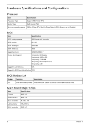
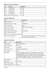
... AMD Socket-FM2 Minimum operating speed 0 MHz (If Stop CPU Clock in Sleep State in BIOS Setup is set to Enabled.) BIOS Item Specification BIOS code programer AMI Kernel with Acer skin BIOS version P01-A0 BIOS ROM type SPI Flash BIOS ROM size 4MB Support protocol SMBIOS(DMI)2.7 Device Boot Support 1st priority: EFI Deivce 2nd...
... AMD Socket-FM2 Minimum operating speed 0 MHz (If Stop CPU Clock in Sleep State in BIOS Setup is set to Enabled.) BIOS Item Specification BIOS code programer AMI Kernel with Acer skin BIOS version P01-A0 BIOS ROM type SPI Flash BIOS ROM size 4MB Support protocol SMBIOS(DMI)2.7 Device Boot Support 1st priority: EFI Deivce 2nd...
Acer Aspire M3420 Desktop Service Guide
Page 17
... users. Audio Interface Item Specification Audio controller AMD FCH HUDSON-D3 Audio controller type ALC662-VD Audio channel 5.1 CHANNEL Audio function control Enable/disable by BIOS Setup Mono or stereo Stereo Compatibility The ALC662-VD supports host audio from Intel chipsets, and also from any combination as long as they match...
... users. Audio Interface Item Specification Audio controller AMD FCH HUDSON-D3 Audio controller type ALC662-VD Audio channel 5.1 CHANNEL Audio function control Enable/disable by BIOS Setup Mono or stereo Stereo Compatibility The ALC662-VD supports host audio from Intel chipsets, and also from any combination as long as they match...
Acer Aspire M3420 Desktop Service Guide
Page 21
... configuration program built into the system ROM, called CMOS RAM. Ask a qualified technician for assistance. Since most systems are prompted ("Run Setup" message) to as "BIOS", "Setup", or "Setup utility" in this case, the system cannot retain configuration values in your system. Before you run the CMOS Setup Utility, make changes...
... configuration program built into the system ROM, called CMOS RAM. Ask a qualified technician for assistance. Since most systems are prompted ("Run Setup" message) to as "BIOS", "Setup", or "Setup utility" in this case, the system cannot retain configuration values in your system. Before you run the CMOS Setup Utility, make changes...
Acer Aspire M3420 Desktop Service Guide
Page 23
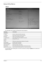
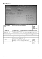
.... Set the date following main setup categories. Chapter 2 15 Product name of the system. Serial number of the system. Parameter System BIOS Version Build Date Processor Core Frequency Count Memory Size Product Name System Serial Number Asset Tag Number System Date System Time (hh:mm:ss...) Description Version number of the CPU installed on the system. Core speed of the BIOS setup utility. In the descriptive table following the hour-minute-second format. Date when the BIOS setup utility was built Type of the menu screenshots, settings in boldface are the default ...
.... Set the date following main setup categories. Chapter 2 15 Product name of the system. Serial number of the system. Parameter System BIOS Version Build Date Processor Core Frequency Count Memory Size Product Name System Serial Number Asset Tag Number System Date System Time (hh:mm:ss...) Description Version number of the CPU installed on the system. Core speed of the BIOS setup utility. In the descriptive table following the hour-minute-second format. Date when the BIOS setup utility was built Type of the menu screenshots, settings in boldface are the default ...
Acer Aspire M3420 Desktop Service Guide
Page 25
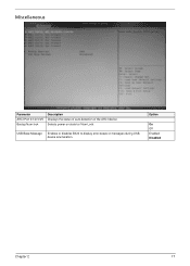
USB Beep Message Enables or disables BIOS to display error beeps or messages during USB device enumeration. Miscellaneous Parameter AHCI Port 0/1/2/3/4/5 Bootup Num-lock Description Displays the status of auto detection of the AHCI device. Selects power on state for Num Lock. Option On Off Enabled Disabled Chapter 2 17
USB Beep Message Enables or disables BIOS to display error beeps or messages during USB device enumeration. Miscellaneous Parameter AHCI Port 0/1/2/3/4/5 Bootup Num-lock Description Displays the status of auto detection of the AHCI device. Selects power on state for Num Lock. Option On Off Enabled Disabled Chapter 2 17
Acer Aspire M3420 Desktop Service Guide
Page 31
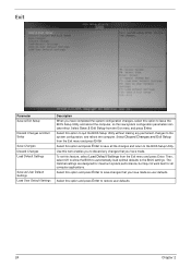
... drives. Press Enter to access the Hard Disk Drive Priority submenu and specify the boot device priority sequence from available network drives. When enabled, the BIOS splash screen displays during startup. Press Enter to access the Optical Disk Drive Priority submenu and specify the boot device priority sequence from available removable...
... drives. Press Enter to access the Hard Disk Drive Priority submenu and specify the boot device priority sequence from available network drives. When enabled, the BIOS splash screen displays during startup. Press Enter to access the Optical Disk Drive Priority submenu and specify the boot device priority sequence from available removable...
Acer Aspire M3420 Desktop Service Guide
Page 32
...you have completed the system configuration changes, select this option and press Enter to save all computer applications. Select this option to the BIOS Setup Utility. Use this feature, select Load Default Settings from the Exit menu and press Enter. Select this option to the system ...configuration, and reboot the computer. Then, select OK to allow the BIOS to automatically load optimal defaults to restore user defaults. 24 Chapter 2 To set this item enables you to discard any permanent changes to...
...you have completed the system configuration changes, select this option and press Enter to save all computer applications. Select this option to the BIOS Setup Utility. Use this feature, select Load Default Settings from the Exit menu and press Enter. Select this option to the system ...configuration, and reboot the computer. Then, select OK to allow the BIOS to automatically load optimal defaults to restore user defaults. 24 Chapter 2 To set this item enables you to discard any permanent changes to...
Acer Aspire M3420 Desktop Service Guide
Page 99
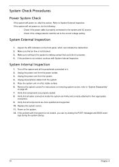
Unplug all components are Acer-qualified and supported. 10. Verify that components are firmly and correctly attached to their appropriate connectors. 9. Verify that air flow is not blocked. 3. Refer to "... system is not evident, you can indicate the malfunction. 2. Inspect the LED indicators on the front panel, which can try viewing the POST messages and BIOS event logs during the system startup. 91 Chapter 4 System External Inspection 1. Turn off the system and all cable connectors inside the system are properly seated...
Unplug all components are Acer-qualified and supported. 10. Verify that components are firmly and correctly attached to their appropriate connectors. 9. Verify that air flow is not blocked. 3. Refer to "... system is not evident, you can indicate the malfunction. 2. Inspect the LED indicators on the front panel, which can try viewing the POST messages and BIOS event logs during the system startup. 91 Chapter 4 System External Inspection 1. Turn off the system and all cable connectors inside the system are properly seated...
Acer Aspire M3420 Desktop Service Guide
Page 100
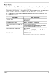
.... CMOS checksum error or CMOS battery loss occurs. Beep codes are used when an error occurs before the system video has been initialized. BIOS is OK. Chapter 4 92 AMIBIOS displays the checkpoints in the bottom right corner of the screen during POST. CMOS damaged. Beep Symptom One ... Continuous one long beep One long beep and two short beeps then repeat. Graphics card error/not installed, graphics card memory error or graphics card BIOS checksum error. Beep Codes Beep codes are used by the system board speaker, commonly referred to as the PC speaker. In most cases, a ...
.... CMOS checksum error or CMOS battery loss occurs. Beep codes are used when an error occurs before the system video has been initialized. BIOS is OK. Chapter 4 92 AMIBIOS displays the checkpoints in the bottom right corner of the screen during POST. CMOS damaged. Beep Symptom One ... Continuous one long beep One long beep and two short beeps then repeat. Graphics card error/not installed, graphics card memory error or graphics card BIOS checksum error. Beep Codes Beep codes are used by the system board speaker, commonly referred to as the PC speaker. In most cases, a ...
Acer Aspire M3420 Desktop Service Guide
Page 101
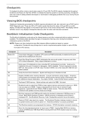
... method islimited, since it . NOTE: Please note that may differ between different platforms based on the bottom right corner of the BIOS. Early chipset initialization is done. Save power-on a LED display. Verify the boot block checksum. Adjust policies and cache first ...given to execute serial flash. Determine whether to it. Store the Uncompressed pointer for debugging. Do additional chipset initialization. Performs main BIOS checksum and updates recovery status accordingly. Checkpoints A checkpoint is either a byte or word value output to I /O initialization is done...
... method islimited, since it . NOTE: Please note that may differ between different platforms based on the bottom right corner of the BIOS. Early chipset initialization is done. Save power-on a LED display. Verify the boot block checksum. Adjust policies and cache first ...given to execute serial flash. Determine whether to it. Store the Uncompressed pointer for debugging. Do additional chipset initialization. Performs main BIOS checksum and updates recovery status accordingly. Checkpoints A checkpoint is either a byte or word value output to I /O initialization is done...
Acer Aspire M3420 Desktop Service Guide
Page 102
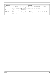
Chapter 4 94 Give control to the next. This range is waking from one platform to BIOS POST (ExecutePOSTKernel). Checkpoint DA DC E1-E8 ECEE Description Restore CPUID value back into register. System is reserved for more information. OEM memory detection/configuration error. The error associated with this value may be different from ACPI S3 state. See POST Code Checkpoints section of document for chipset vendors & system manufacturers.
Chapter 4 94 Give control to the next. This range is waking from one platform to BIOS POST (ExecutePOSTKernel). Checkpoint DA DC E1-E8 ECEE Description Restore CPUID value back into register. System is reserved for more information. OEM memory detection/configuration error. The error associated with this value may be different from ACPI S3 state. See POST Code Checkpoints section of document for chipset vendors & system manufacturers.
Acer Aspire M3420 Desktop Service Guide
Page 103
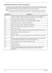
...reading the recovery file cluster by the recovery file. Check the validity of the recovery file configuration to the current configuration of the BIOS. Make flash write disabled. Checkpoints maychange due to find the clusters occupied by cluster. Disable L1 cache. NOTE: Checkpoints may occur ... equal the found . Erase the flash part Program the flash part. Attempt to read from floppy. Disable ATAPI hardware. Verify that a BIOS recovery needs to F000 ROM at F000:FFF0h. 95 Chapter 4 Restore CPUID value back into register. Set up floppy controller and data....
...reading the recovery file cluster by the recovery file. Check the validity of the recovery file configuration to the current configuration of the BIOS. Make flash write disabled. Checkpoints maychange due to find the clusters occupied by cluster. Disable L1 cache. NOTE: Checkpoints may occur ... equal the found . Erase the flash part Program the flash part. Attempt to read from floppy. Disable ATAPI hardware. Verify that a BIOS recovery needs to F000 ROM at F000:FFF0h. 95 Chapter 4 Restore CPUID value back into register. Set up floppy controller and data....
Acer Aspire M3420 Desktop Service Guide
Page 104
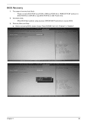
Before recovering BIOS, please change "Reset NVRAM" item form "Enabled" to recover BIOS. 3. Recovery Menu and Step: a. Automatic mode: • When BIOS flash crashed, using recovery CDROM/USB Thumb drive to "Disabled". Chapter 4 96 BIOS Recovery 1. The usage of recovery boot block: • Please re-name BIOS ROM (xxxx.ROM or 2MB size ROM) file to "AMIBOOT.ROM" and burn in BIOS ROM file to CDROM or copy BIOS ROM file to USB Thumb drive. 2.
Before recovering BIOS, please change "Reset NVRAM" item form "Enabled" to recover BIOS. 3. Recovery Menu and Step: a. Automatic mode: • When BIOS flash crashed, using recovery CDROM/USB Thumb drive to "Disabled". Chapter 4 96 BIOS Recovery 1. The usage of recovery boot block: • Please re-name BIOS ROM (xxxx.ROM or 2MB size ROM) file to "AMIBOOT.ROM" and burn in BIOS ROM file to CDROM or copy BIOS ROM file to USB Thumb drive. 2.
Acer Aspire M3420 Desktop Service Guide
Page 108
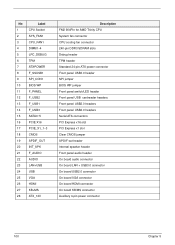
No Label 1 CPU Socket 2 SYS_FAN1 3 CPU_FAN1 4 DIMM1~4 5 LPC_DEBUG 6 TPM 7 ATXPOWER 8 F_SSUSB1 9 SPI_CON1 10 BIOS WP 11 F_PANEL 12 F_USB2 13 F_USB1 14 F_USB3 15 SATA0~5 16 PCIE X16 17 PCIE_X1_1~3 18 CMOS 19 SPDIF_OUT 20 INT_SPK 21 F_AUDIO 22... CPU cooling fan connector 240-pin DDR3 SDRAM slots Debug header TPM header Standard 24-pin ATX power connector Front panel USB3.0 header SPI jumper BIOS WP jumper Front panel switch/LED header Front panel USB cardreader headers Front panel USB2.0 headers Front panel USB2.0 headers Serial ATA connectors PCI Express...
No Label 1 CPU Socket 2 SYS_FAN1 3 CPU_FAN1 4 DIMM1~4 5 LPC_DEBUG 6 TPM 7 ATXPOWER 8 F_SSUSB1 9 SPI_CON1 10 BIOS WP 11 F_PANEL 12 F_USB2 13 F_USB1 14 F_USB3 15 SATA0~5 16 PCIE X16 17 PCIE_X1_1~3 18 CMOS 19 SPDIF_OUT 20 INT_SPK 21 F_AUDIO 22... CPU cooling fan connector 240-pin DDR3 SDRAM slots Debug header TPM header Standard 24-pin ATX power connector Front panel USB3.0 header SPI jumper BIOS WP jumper Front panel switch/LED header Front panel USB cardreader headers Front panel USB2.0 headers Front panel USB2.0 headers Serial ATA connectors PCI Express...


