Acer Aspire M3410 Desktop Service Guide
Page 6
... the responsible personnel/channel to provide you with all technical information relating to extend the functionality of a machine (e.g. add-on your regional Acer office to those given in the FRU list of customer machines. In such cases, please contact your regional office MAY have a DIFFERENT...Please note WHEN ORDERING FRU PARTS, that you should check the most up-to-date information available on card, modem, or extra memory capability). vi Service Guide Coverage This Service Guide provides you with further technical details. You MUST use the list provided by your regional...
... the responsible personnel/channel to provide you with all technical information relating to extend the functionality of a machine (e.g. add-on your regional Acer office to those given in the FRU list of customer machines. In such cases, please contact your regional office MAY have a DIFFERENT...Please note WHEN ORDERING FRU PARTS, that you should check the most up-to-date information available on card, modem, or extra memory capability). vi Service Guide Coverage This Service Guide provides you with further technical details. You MUST use the list provided by your regional...
Acer Aspire M3410 Desktop Service Guide
Page 7
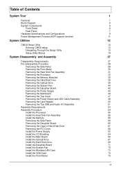
...28 Removing the Side Panel 29 Removing the Front Bezel 30 Removing the Heat Sink Fan Assembly 31 Removing the Processor 33 Removing the Memory Modules 35 Removing the Hard Disk Drive 36 Removing the Optical Drive 38 Removing the System Fan 40 Removing the Daughter Board 42 ... and Audio I/O Assembly 51 Assembly Requirements 53 Assembly Procedure 54 Install the Processor 55 Install the Heat Sink Fan Assembly 56 Install the Memory 58 Romoving the Side Panel 59 Removing the Daughter Board 60 Removing the Cage of Hard Disk Drive 61 Removing the PCI Cover 62 ...
...28 Removing the Side Panel 29 Removing the Front Bezel 30 Removing the Heat Sink Fan Assembly 31 Removing the Processor 33 Removing the Memory Modules 35 Removing the Hard Disk Drive 36 Removing the Optical Drive 38 Removing the System Fan 40 Removing the Daughter Board 42 ... and Audio I/O Assembly 51 Assembly Requirements 53 Assembly Procedure 54 Install the Processor 55 Install the Heat Sink Fan Assembly 56 Install the Memory 58 Romoving the Side Panel 59 Removing the Daughter Board 60 Removing the Cage of Hard Disk Drive 61 Removing the PCI Cover 62 ...
Acer Aspire M3410 Desktop Service Guide
Page 9
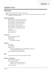
PCB • 4 Layer uATX form factor 9.6in X 9.6in (24.38cm X 24.38cm) Memory subsystem • Socket Type: DDR III connector • Socket Quantity: 4 DIMMs • Channel A: Slot 2, 4; Channel B: Slot 1, 3 • Different colors for your reference only. The exact ...
PCB • 4 Layer uATX form factor 9.6in X 9.6in (24.38cm X 24.38cm) Memory subsystem • Socket Type: DDR III connector • Socket Quantity: 4 DIMMs • Channel A: Slot 2, 4; Channel B: Slot 1, 3 • Different colors for your reference only. The exact ...
Acer Aspire M3410 Desktop Service Guide
Page 10
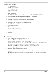
...8226; Speed support: 1333MHz • Capacity support: • DDR III un-buffered non-ECC DIMM support. • 1GB to measure VGA follow Acer SOP Audio • Chip : HD audio codec ALC662-VC HD codec 5.1 • Connectors support: • Rear 3 jack follow HD audio ...bezel • Models are listed on AVLC Graphics card • No mechanical retriction to support for double slot, full length graphics cards in 2 same memory size DDR III memory module. • Should meet Microsoft Windows Logo Program Device Requirements: Audio-0002 • 1 S/PDIF-out header (1*4) • 1 front panel ...
...8226; Speed support: 1333MHz • Capacity support: • DDR III un-buffered non-ECC DIMM support. • 1GB to measure VGA follow Acer SOP Audio • Chip : HD audio codec ALC662-VC HD codec 5.1 • Connectors support: • Rear 3 jack follow HD audio ...bezel • Models are listed on AVLC Graphics card • No mechanical retriction to support for double slot, full length graphics cards in 2 same memory size DDR III memory module. • Should meet Microsoft Windows Logo Program Device Requirements: Audio-0002 • 1 S/PDIF-out header (1*4) • 1 front panel ...
Acer Aspire M3410 Desktop Service Guide
Page 12
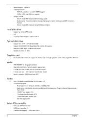
On-board connectors • 1 AM3 CPU socket • 4 DDR3 memory sockets • 1 PCI Express x16 slot • 2 PCI Express x1 slot • 1 PCI slots • 6 SATA2 connectors • Four 2x5-pin Intel FPIO specification USB ... clear CMOS • 1 on board buzzer • 2 reserved 2-pin GPIO connector System BIOS • Size: 8Mbit • AMI Kernel with Acer skin/copyright Power supply • 300W in stable mode (Acer Assign System Power Unit) • Support 82+ PSU for EnergyStar 5.0 complaint • Design for RS880P+SB810 series chipset compatible system •...
On-board connectors • 1 AM3 CPU socket • 4 DDR3 memory sockets • 1 PCI Express x16 slot • 2 PCI Express x1 slot • 1 PCI slots • 6 SATA2 connectors • Four 2x5-pin Intel FPIO specification USB ... clear CMOS • 1 on board buzzer • 2 reserved 2-pin GPIO connector System BIOS • Size: 8Mbit • AMI Kernel with Acer skin/copyright Power supply • 300W in stable mode (Acer Assign System Power Unit) • Support 82+ PSU for EnergyStar 5.0 complaint • Design for RS880P+SB810 series chipset compatible system •...
Acer Aspire M3410 Desktop Service Guide
Page 17
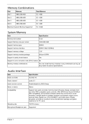
...audio controller from the Intel ICH series chipset, and also from any combination as long as they match the above specifications. Memory Combinations Slot Memory Total Memory Slot 1 1MB,2GB,4GB 1G ~4GB Slot 2 1MB,2GB,4GB 1G ~4GB Slot 3 1MB,2GB,4GB 1G ~...1MB,2GB,4GB 1G ~4GB Maximum System Memory Supported 1G~16GB System Memory Item Specification Memory slot number 4 slot Support Memory size per socket 1GB/2GB/4GB Support memory type DDRIII Support memory interface DDRIII 1066/1333MHz Support memory voltage 1.5V Support memory module package 240-pin DDRIII Support to...
...audio controller from the Intel ICH series chipset, and also from any combination as long as they match the above specifications. Memory Combinations Slot Memory Total Memory Slot 1 1MB,2GB,4GB 1G ~4GB Slot 2 1MB,2GB,4GB 1G ~4GB Slot 3 1MB,2GB,4GB 1G ~...1MB,2GB,4GB 1G ~4GB Maximum System Memory Supported 1G~16GB System Memory Item Specification Memory slot number 4 slot Support Memory size per socket 1GB/2GB/4GB Support memory type DDRIII Support memory interface DDRIII 1066/1333MHz Support memory voltage 1.5V Support memory module package 240-pin DDRIII Support to...
Acer Aspire M3410 Desktop Service Guide
Page 20
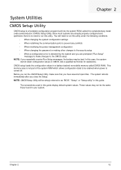
... the Setup. Chapter 2 12 You will be simply referred to as "BIOS", "Setup", or "Setup utility" in a battery-backed nonvolatile memory called the complementary metaloxide semiconductor (CMOS) Setup Utility. This memory area is not part of the system RAM which allows configuration data to run the CMOS Setup Utility, make changes to...
... the Setup. Chapter 2 12 You will be simply referred to as "BIOS", "Setup", or "Setup utility" in a battery-backed nonvolatile memory called the complementary metaloxide semiconductor (CMOS) Setup Utility. This memory area is not part of the system RAM which allows configuration data to run the CMOS Setup Utility, make changes to...
Acer Aspire M3410 Desktop Service Guide
Page 23
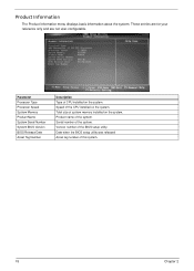
Product name of the BIOS setup utility. Version number of the system. Parameter Processor Type Processor Speed System Memory Product Name System Serial Number System BIOS Version BIOS Release Date Asset Tag Number Description Type of this system. 15 Chapter 2 Product Information The ...when the BIOS setup utility was released Asset tag number of CPU installed on the system. Total size of the system. Serial number of system memory installed on the system. Speed of the CPU installed on the system. These entries are for your reference only and are not user-configurable.
Product name of the BIOS setup utility. Version number of the system. Parameter Processor Type Processor Speed System Memory Product Name System Serial Number System BIOS Version BIOS Release Date Asset Tag Number Description Type of this system. 15 Chapter 2 Product Information The ...when the BIOS setup utility was released Asset tag number of CPU installed on the system. Total size of the system. Serial number of system memory installed on the system. Speed of the CPU installed on the system. These entries are for your reference only and are not user-configurable.
Acer Aspire M3410 Desktop Service Guide
Page 26
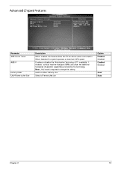
Enables or disables the Virtualization Technology (VT) availability. Select a Video memory size Select a Frame buffe size Option Enabled Disabled Enabled Disabled Auto Auto Chapter 2 18 Note: A full reset is required to reduce power consumption. Advanced Chipset ...
Enables or disables the Virtualization Technology (VT) availability. Select a Video memory size Select a Frame buffe size Option Enabled Disabled Enabled Disabled Auto Auto Chapter 2 18 Note: A full reset is required to reduce power consumption. Advanced Chipset ...

Acer Aspire M3410 Desktop Service Guide
Page 32
Load Default Settings The Load Default Settings menu allows you choose to load the default settings for all BIOS setup parameters. If you are quite demanding in terms of low-performance components and you to load these settings, the system might not function properly. Setup defaults are using low-speed memory chips or other kinds of resources consumption. Chapter 2 24
Load Default Settings The Load Default Settings menu allows you choose to load the default settings for all BIOS setup parameters. If you are quite demanding in terms of low-performance components and you to load these settings, the system might not function properly. Setup defaults are using low-speed memory chips or other kinds of resources consumption. Chapter 2 24
Acer Aspire M3410 Desktop Service Guide
Page 43
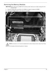
Note:Circuit boards >10 cm² has been highlighted with the yellow rectangle as above image shows. Please detach the Circuit boards and follow local regulations for disposal. Removing the Memory Modules IMPORTANT:Before removing any DIMM from the M/B(2). Chapter 3 35 Press the holding clips on both sides of all important data. 1. Gently pull the DIMM upward to pull it away from the memory board, make sure to create a backup file of the DIMM slot outward to release the DIMM(1). 2.
Note:Circuit boards >10 cm² has been highlighted with the yellow rectangle as above image shows. Please detach the Circuit boards and follow local regulations for disposal. Removing the Memory Modules IMPORTANT:Before removing any DIMM from the M/B(2). Chapter 3 35 Press the holding clips on both sides of all important data. 1. Gently pull the DIMM upward to pull it away from the memory board, make sure to create a backup file of the DIMM slot outward to release the DIMM(1). 2.
Acer Aspire M3410 Desktop Service Guide
Page 66
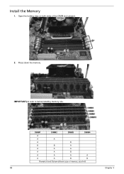
Press down the memory. DIMM1 DIMM2 DIMM3 DIMM4 A A A A B B B A A A A A A B A A A A A A B B Remark:A and B show different size of the DIMM slot outward. 2. Install the Memory 1. Open the holding clips on both sides of memory, size:A>B 58 Chapter 3 IMPORTANT:pls refer to below installing memory rule.
Press down the memory. DIMM1 DIMM2 DIMM3 DIMM4 A A A A B B B A A A A A A B A A A A A A B B Remark:A and B show different size of the DIMM slot outward. 2. Install the Memory 1. Open the holding clips on both sides of memory, size:A>B 58 Chapter 3 IMPORTANT:pls refer to below installing memory rule.
Acer Aspire M3410 Desktop Service Guide
Page 87
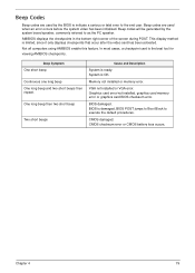
... using AMIBIOS enable this feature. Beep Symptom One short beep Continuous one long beep One long beep and two short beeps then repeat. Memory not installed or memory error. BIOS is the best tool for viewing AMIBIOS checkpoints. In most cases, a checkpoint card is damaged, BIOS POST jumps to... the bottom right corner of the screen during POST. CMOS damaged. This display method is ready. Graphics card error/not installed, graphics card memory error or graphics card BIOS checksum error. Beep Codes Beep codes are used by the system board speaker, commonly referred to as the PC ...
... using AMIBIOS enable this feature. Beep Symptom One short beep Continuous one long beep One long beep and two short beeps then repeat. Memory not installed or memory error. BIOS is the best tool for viewing AMIBIOS checkpoints. In most cases, a checkpoint card is damaged, BIOS POST jumps to... the bottom right corner of the screen during POST. CMOS damaged. This display method is ready. Graphics card error/not installed, graphics card memory error or graphics card BIOS checksum error. Beep Codes Beep codes are used by the system board speaker, commonly referred to as the PC ...
Acer Aspire M3410 Desktop Service Guide
Page 88
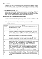
...referred to as -RAM functionality is enabled at this point. Bootblock Initialization Code Checkpoints The Bootblock initialization code sets up the chipset,memory, and other CPU critical initialization. NMI is necessary,control flows to checkpoint E0. Set stack. Checkpoint sare very useful in aiding ... and updates recovery status accordingly. These are ISA or PCI add-in PMM. The Bootblock-Runtime interface module is moved to system memory and control is currently executing. Checkpoints A checkpoint is either a byte or word value output to I/O port 80h.The BIOS outputs...
...referred to as -RAM functionality is enabled at this point. Bootblock Initialization Code Checkpoints The Bootblock initialization code sets up the chipset,memory, and other CPU critical initialization. NMI is necessary,control flows to checkpoint E0. Set stack. Checkpoint sare very useful in aiding ... and updates recovery status accordingly. These are ISA or PCI add-in PMM. The Bootblock-Runtime interface module is moved to system memory and control is currently executing. Checkpoints A checkpoint is either a byte or word value output to I/O port 80h.The BIOS outputs...
Acer Aspire M3410 Desktop Service Guide
Page 89
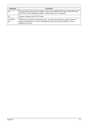
See POST Code Checkpoints section of document for chipset vendors & system manufacturers. This range is waking from one platform to BIOS POST (ExecutePOSTKernel). Give control to the next. The error associated with this value may be different from ACPI S3 state. OEM memory detection/configuration error. Chapter 4 81 System is reserved for more information. Checkpoint DA DC E1-E8 ECEE Description Restore CPUID value back into register.
See POST Code Checkpoints section of document for chipset vendors & system manufacturers. This range is waking from one platform to BIOS POST (ExecutePOSTKernel). Give control to the next. The error associated with this value may be different from ACPI S3 state. OEM memory detection/configuration error. Chapter 4 81 System is reserved for more information. Checkpoint DA DC E1-E8 ECEE Description Restore CPUID value back into register.


