Service Guide
Page 7
...30 Removing the Processor 32 Removing the VGA Card 33 Removing the Wireless Card 35 Removing the Memory Modules 36 Removing the System Fan 37 Removing the Daughter Board 38 Removing Other Side Panel 40 Removing the Hard Disk Drive 41 Removing the Removable Hard Disk Drive 43 Removing the Optical Drive 46 Removing the Power Supply 48 Removing the Motherboard 49 Removing the Card Reader 52 Removing the Top Cover 54 Removing the Power Switch and LED Cable Assembly 55 Removing the Front I/O and USB Board 57 System Troubleshooting 59 Hardware Diagnostic Procedure...
...30 Removing the Processor 32 Removing the VGA Card 33 Removing the Wireless Card 35 Removing the Memory Modules 36 Removing the System Fan 37 Removing the Daughter Board 38 Removing Other Side Panel 40 Removing the Hard Disk Drive 41 Removing the Removable Hard Disk Drive 43 Removing the Optical Drive 46 Removing the Power Supply 48 Removing the Motherboard 49 Removing the Card Reader 52 Removing the Top Cover 54 Removing the Power Switch and LED Cable Assembly 55 Removing the Front I/O and USB Board 57 System Troubleshooting 59 Hardware Diagnostic Procedure...
Service Guide
Page 9
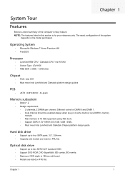
...*244mm / 4 Layers Memory subsystem • DDR3 * 4 • Design requirement: • 2 channels, 2 DIMMs per channel. Chapter 1 1 Different colors for your reference only. Hard disk drive • Support up to two SATA 5.25" standard ODD. • Support DVD-ROM, DVD-SuperMulti, BD-combo, BD-rewrite, • Maximum ODD depth to four SATA ports. 3.5", 25.4mm. • Capacity and models are listed on FRU list. Optical disk drive • Support up to...
...*244mm / 4 Layers Memory subsystem • DDR3 * 4 • Design requirement: • 2 channels, 2 DIMMs per channel. Chapter 1 1 Different colors for your reference only. Hard disk drive • Support up to two SATA 5.25" standard ODD. • Support DVD-ROM, DVD-SuperMulti, BD-combo, BD-rewrite, • Maximum ODD depth to four SATA ports. 3.5", 25.4mm. • Capacity and models are listed on FRU list. Optical disk drive • Support up to...

Service Guide
Page 10
...slots • 1 PCI slot Serial ATA controller • Connector Type: SATA connector • Connector Quantity:6 • Storage Type support: • HDD : Support RAID 0/1/5/10 • Blue Ray ODD • AHCI mode supported for internal SATA port Rear I/O connectors • 1 * PS/2 keyboard & PS/2 mouse connector • 6 * USB ports • 1 * RJ45 LAN connector • 1 * Audio port (Line in, microphone in, line out) Internal I/O Connectors & Headers • 1 * 1156 socket • 1 * SUBASSY.STEEL for LGA 1156 CPU • 1 * 24-pin ATX PWR connector • 1 * H2X4 Power Supply...
...slots • 1 PCI slot Serial ATA controller • Connector Type: SATA connector • Connector Quantity:6 • Storage Type support: • HDD : Support RAID 0/1/5/10 • Blue Ray ODD • AHCI mode supported for internal SATA port Rear I/O connectors • 1 * PS/2 keyboard & PS/2 mouse connector • 6 * USB ports • 1 * RJ45 LAN connector • 1 * Audio port (Line in, microphone in, line out) Internal I/O Connectors & Headers • 1 * 1156 socket • 1 * SUBASSY.STEEL for LGA 1156 CPU • 1 * 24-pin ATX PWR connector • 1 * H2X4 Power Supply...

Service Guide
Page 13
... open HDD bay door and access the removable HDD. 2 USB 2.0 ports 9 MS/MS PRO slot 3 Master optical drive crab 10 SD/MMC(Secure Digital/MultiMedia Card)slot 4 Slave optical drive crab 11 Master optical drive button Press to open master optical drive crab and access the master optical drive. 5 XD(XD-Picture) slot 12 Slave optical drive button Press to open slave optical drive crab and access the slave optical drive. 6 Micro SD slot 13 Microphone-in jack 7 CF I/II (CompactFlash Type I/II) slot 14 Headphone/Speaker...
... open HDD bay door and access the removable HDD. 2 USB 2.0 ports 9 MS/MS PRO slot 3 Master optical drive crab 10 SD/MMC(Secure Digital/MultiMedia Card)slot 4 Slave optical drive crab 11 Master optical drive button Press to open master optical drive crab and access the master optical drive. 5 XD(XD-Picture) slot 12 Slave optical drive button Press to open slave optical drive crab and access the slave optical drive. 6 Micro SD slot 13 Microphone-in jack 7 CF I/II (CompactFlash Type I/II) slot 14 Headphone/Speaker...
Service Guide
Page 15
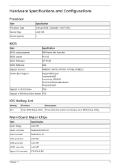
....0 Device Boot Support Support BBS spec 1st priority:HDD 2nd priority:CD&DVD 3th priority:Removable device 4th priority:LAN Support to LS-120 drive YES Support to BIOS boot block feature YES IOS Hotkey List Hotkey Function Description Del Enter BIOS Setup Utility Press while the system is booting to enter BIOS Setup Utility. Main Board Major Chips Item Specification North Bridge Intel H57 Audio controller Realtek ALC662-VC LAN controller Realtek 8111E VGA controller Intel H57 USB controller Intel H57 SATA controller Intel H57 Super I/O controller...
....0 Device Boot Support Support BBS spec 1st priority:HDD 2nd priority:CD&DVD 3th priority:Removable device 4th priority:LAN Support to LS-120 drive YES Support to BIOS boot block feature YES IOS Hotkey List Hotkey Function Description Del Enter BIOS Setup Utility Press while the system is booting to enter BIOS Setup Utility. Main Board Major Chips Item Specification North Bridge Intel H57 Audio controller Realtek ALC662-VC LAN controller Realtek 8111E VGA controller Intel H57 USB controller Intel H57 SATA controller Intel H57 Super I/O controller...
Service Guide
Page 16
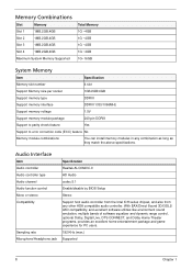
... System Memory Item Specification Memory slot number 4 slot Support Memory size per socket 1GB/2GB/4GB Support memory type DDRIII Support memory interface DDRIII 1333/1066MHz Support memory voltage 1.5V Support memory module package 240-pin DDRIII Support to parity check feature Yes Support to error correction code (ECC) feature No Memory module combinations You can install memory modules in any other HDA compatible audio controller. With EAX/Direct Sound 3D/I3DL2/ A3D compatibility, and excellent software utilities like environment sound...
... System Memory Item Specification Memory slot number 4 slot Support Memory size per socket 1GB/2GB/4GB Support memory type DDRIII Support memory interface DDRIII 1333/1066MHz Support memory voltage 1.5V Support memory module package 240-pin DDRIII Support to parity check feature Yes Support to error correction code (ECC) feature No Memory module combinations You can install memory modules in any other HDA compatible audio controller. With EAX/Direct Sound 3D/I3DL2/ A3D compatibility, and excellent software utilities like environment sound...
Service Guide
Page 17
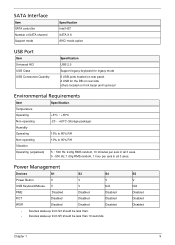
...Disabled Disabled Disabled Chapter 1 9 SATA Interface Item SATA controller Number of SATA channel Support mode Specification Intel H57 SATA X 6 AHCI mode option USB Port Item Universal HCI USB Class USB Connectors Quantity Specification USB 2.0 Support legacy keyboard for legacy mode 6 USB ports located on rear panel. 2 USB for the DB on rear side others located on front bezel and top bezel Environmental Requirements Item Specification Temperature Operating +5°C ~ +35°C Non-operating -20 ~ +60°C (Storage package) Humidity Operating 15% to 80% RH Non-operating...
...Disabled Disabled Disabled Chapter 1 9 SATA Interface Item SATA controller Number of SATA channel Support mode Specification Intel H57 SATA X 6 AHCI mode option USB Port Item Universal HCI USB Class USB Connectors Quantity Specification USB 2.0 Support legacy keyboard for legacy mode 6 USB ports located on rear panel. 2 USB for the DB on rear side others located on front bezel and top bezel Environmental Requirements Item Specification Temperature Operating +5°C ~ +35°C Non-operating -20 ~ +60°C (Storage package) Humidity Operating 15% to 80% RH Non-operating...

Service Guide
Page 18
... in,keyboard an mouse for APM mode. • Resume recovery time :7-10sec Suspend Mode • Independent power management timer(2-120minutes,time step=10minute)or pushing extern switch button. • CPU goes into SMM • CPU asserts STPCLK# and goes into the Stop Grant State. • LED on panel turns amber colour. • Hard disk drive goes into SLEEP mode (for ATA standard interface). • Disable H-sync and V-sync signals to control the...
... in,keyboard an mouse for APM mode. • Resume recovery time :7-10sec Suspend Mode • Independent power management timer(2-120minutes,time step=10minute)or pushing extern switch button. • CPU goes into SMM • CPU asserts STPCLK# and goes into the Stop Grant State. • LED on panel turns amber colour. • Hard disk drive goes into SLEEP mode (for ATA standard interface). • Disable H-sync and V-sync signals to control the...
Service Guide
Page 19
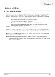
... Chapter 2 System Utilities CMOS Setup Utility CMOS setup is a hardware configuration program built into the system ROM, called CMOS RAM. In this guide display default system values. Before you run this utility under the following conditions. • When changing the system configuration settings • When redefining the communication ports to prevent any conflicts • When modifying the power management configuration • When changing the password or making other changes to the security setup • When a configuration error is detected by...
... Chapter 2 System Utilities CMOS Setup Utility CMOS setup is a hardware configuration program built into the system ROM, called CMOS RAM. In this guide display default system values. Before you run this utility under the following conditions. • When changing the system configuration settings • When redefining the communication ports to prevent any conflicts • When modifying the power management configuration • When changing the password or making other changes to the security setup • When a configuration error is detected by...
Service Guide
Page 22
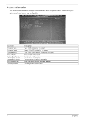
... only and are not user-configurable. Product name of system memory installed on the system. Version number of the CPU installed on the system. Speed of the BIOS setup utility. Serial number of this system. 14 Chapter 2 Date when the BIOS setup utility was released Asset tag number of the system. Parameter Processor Type Processor Speed System Memory Product Name System Serial Number System BIOS Version BIOS Release Date Asset Tag Number Description Type of CPU installed on the system...
... only and are not user-configurable. Product name of system memory installed on the system. Version number of the CPU installed on the system. Speed of the BIOS setup utility. Serial number of this system. 14 Chapter 2 Date when the BIOS setup utility was released Asset tag number of the system. Parameter Processor Type Processor Speed System Memory Product Name System Serial Number System BIOS Version BIOS Release Date Asset Tag Number Description Type of CPU installed on the system...

Service Guide
Page 24
... key is active when your system On is started. Advanced BIOS Feature Quick Boot Quiet Boot 1st/2nd/3rd/4th Boot Device Hard Disk Drive Priority Optical Disk Drive Priority Removable Device Priority Network Drives Priority Bootup Num-Lock USB Beep Message Allows you to decrease the time it takes to access the Optical Disk Drive Priority submenu and specify the boot device priority sequence from available optical drives. Press Enter to display error beeps or messages during startup. When disabled, the diagnostic screen displays during startup. Disabled Enabled...
... key is active when your system On is started. Advanced BIOS Feature Quick Boot Quiet Boot 1st/2nd/3rd/4th Boot Device Hard Disk Drive Priority Optical Disk Drive Priority Removable Device Priority Network Drives Priority Bootup Num-Lock USB Beep Message Allows you to decrease the time it takes to access the Optical Disk Drive Priority submenu and specify the boot device priority sequence from available optical drives. Press Enter to display error beeps or messages during startup. When disabled, the diagnostic screen displays during startup. Disabled Enabled...

Service Guide
Page 26
... be used to force a HDD formatted drive to boot as harddrive. Enables or disables the onboard LAN controller. Enables or disables the onboard USB controller. Enables or disables the onboard audio controller. Integrated Peripherals Parameter Onboard SATA Controller Onboard SATA Mode Onboard USB Controller Legacy USB Support USB Storage Emulation Onboard Audio Controller Onboard LAN Controller Onboard LAN Option ROM Description Enables or disables the onboard SATA controller. Option Enabled Disabled RAID Native IDE Enabled Disabled Enabled Disabled Auto Floppy Hard Disk Enabled Disabled...
... be used to force a HDD formatted drive to boot as harddrive. Enables or disables the onboard LAN controller. Enables or disables the onboard USB controller. Enables or disables the onboard audio controller. Integrated Peripherals Parameter Onboard SATA Controller Onboard SATA Mode Onboard USB Controller Legacy USB Support USB Storage Emulation Onboard Audio Controller Onboard LAN Controller Onboard LAN Option ROM Description Enables or disables the onboard SATA controller. Option Enabled Disabled RAID Native IDE Enabled Disabled Enabled Disabled Auto Floppy Hard Disk Enabled Disabled...

Service Guide
Page 67
... "Power System check" and "Beep Codes" to determine which corrective action to recreate the failure by running the diagnostic tests or repeating thesame operation. 3. Obtain the failing symptoms in this chapter are only intended to test Acer products. Chapter 4 59 Verify the symptoms by attempting to perform. Chapter 4 System Troubleshooting This chapter provides instructions on how to troubleshoot system hardware problems. Hardware Diagnostic Procedure IMPORTANT:The diagnostic tests described...
... "Power System check" and "Beep Codes" to determine which corrective action to recreate the failure by running the diagnostic tests or repeating thesame operation. 3. Obtain the failing symptoms in this chapter are only intended to test Acer products. Chapter 4 59 Verify the symptoms by attempting to perform. Chapter 4 System Troubleshooting This chapter provides instructions on how to troubleshoot system hardware problems. Hardware Diagnostic Procedure IMPORTANT:The diagnostic tests described...
Service Guide
Page 70
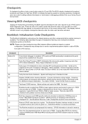
... type of I/O port 80h on system configuration.Checkpoints may change due to vendor requirements,system chipset or option ROMs from ROM to lower system memory and control is tested. Copying Main BIOS into register. Determine whether to flat mode with 4GB limit and GA20 enabled. Restore CPUID value back into memory. Do additional chipset initialization. Performs main BIOS checksum and updates recovery status accordingly. System will be enabled from ROM...
... type of I/O port 80h on system configuration.Checkpoints may change due to vendor requirements,system chipset or option ROMs from ROM to lower system memory and control is tested. Copying Main BIOS into register. Determine whether to flat mode with 4GB limit and GA20 enabled. Restore CPUID value back into memory. Do additional chipset initialization. Performs main BIOS checksum and updates recovery status accordingly. System will be enabled from ROM...
Service Guide
Page 72
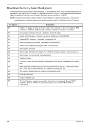
.... Set up floppy controller and data. Jump back to read from add-in PCI devices. Make flash write enabled through chipset and OEM specific method. Erase the flash part Program the flash part. Restore CPUID value back into register. Attempt to checkpoint E9. Check the validity of the BIOS. Detect proper flash part. Verify that the found . Make flash write disabled. Disable ATAPI hardware. Enable ATAPI hardware. DMA controller is initialized. 8259 interrupt controller is enabled. Recovery file...
.... Set up floppy controller and data. Jump back to read from add-in PCI devices. Make flash write enabled through chipset and OEM specific method. Erase the flash part Program the flash part. Restore CPUID value back into register. Attempt to checkpoint E9. Check the validity of the BIOS. Detect proper flash part. Verify that the found . Make flash write disabled. Disable ATAPI hardware. Enable ATAPI hardware. DMA controller is initialized. 8259 interrupt controller is enabled. Recovery file...

Service Guide
Page 73
... support Boot function is healthy. 2. Don't do anything during the recovery function to be "AMIBOOT.ROM". 4-3. Insert the recovery device to execute recovery function media: FDD / USB storage / ODD. 3. Allow to system and then power on the system. 4-4. The system will execute 1~3 minutes. 4-6. Chapter 4 65 If the recovery function run normally, the recovery function will auto reboot after the recovery function finished and please enter the setup menu...
... support Boot function is healthy. 2. Don't do anything during the recovery function to be "AMIBOOT.ROM". 4-3. Insert the recovery device to execute recovery function media: FDD / USB storage / ODD. 3. Allow to system and then power on the system. 4-4. The system will execute 1~3 minutes. 4-6. Chapter 4 65 If the recovery function run normally, the recovery function will auto reboot after the recovery function finished and please enter the setup menu...
Service Guide
Page 76
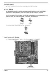
... pin are numbered. This illustration shows a 3-pin jumper.Pins 1 and 2 are Placed on bothpins, the jumper is SHORT. Setting Jumper Use the motherboard jumpers to set system configuration options. When setting the jumpers, ensure that the jumper caps are SHORT. Checking Jumper Settings The following illustration shows the location of the mainboard. Pin 1 islabeled. Jumpers with more Than one pin, the jumper is placed on the correct pins. The illustrations show a 2-pin jumper.When the jumper cap is OPEN. Jumper Setting...
... pin are numbered. This illustration shows a 3-pin jumper.Pins 1 and 2 are Placed on bothpins, the jumper is SHORT. Setting Jumper Use the motherboard jumpers to set system configuration options. When setting the jumpers, ensure that the jumper caps are SHORT. Checking Jumper Settings The following illustration shows the location of the mainboard. Pin 1 islabeled. Jumpers with more Than one pin, the jumper is placed on the correct pins. The illustrations show a 2-pin jumper.When the jumper cap is OPEN. Jumper Setting...
Service Guide
Page 90
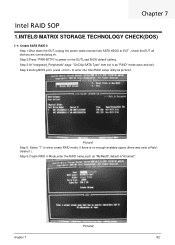
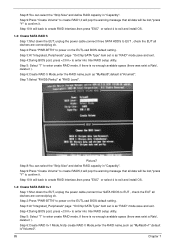
... enter into Intel RAID setup utility,as "MyRaid0",default is"Volume0". Step 6:Create RAID 0 Mode,enter the RAID name,such as picture1. Picture2 chapter 7 82 Chapter 7 Intel RAID SOP 1.INTEL® MATRIX STORAGE TECHNOLOGY CHECK(DOS) 1-1: Create SATA RAID 0 Step 1:Shut down the EUT, unplug the power cable,connect two SATA HDDS to power on the EUT,Load BIOS default setting . Step 4:During BIOS post, press to enter create RAID mode ,if there is as "RAID" mode...
... enter into Intel RAID setup utility,as "MyRaid0",default is"Volume0". Step 6:Create RAID 0 Mode,enter the RAID name,such as picture1. Picture2 chapter 7 82 Chapter 7 Intel RAID SOP 1.INTEL® MATRIX STORAGE TECHNOLOGY CHECK(DOS) 1-1: Create SATA RAID 0 Step 1:Shut down the EUT, unplug the power cable,connect two SATA HDDS to power on the EUT,Load BIOS default setting . Step 4:During BIOS post, press to enter create RAID mode ,if there is as "RAID" mode...
Service Guide
Page 93
... and install OS. 1-3: Create SATA RAID 5 Step 1:Shut down the EUT, unplug the power cable,connect four SATA HDDS to EUT , check the EUT all data will be lost ,"press "Y" to power on the EUT,Load BIOS default setting . Step 2:Press "PWR-BTTN" to confirm it will pop the warning message that all devices are connect/plug ok. Step 9:Press "Create Volume" to enter into Intel RAID setup utility...
... and install OS. 1-3: Create SATA RAID 5 Step 1:Shut down the EUT, unplug the power cable,connect four SATA HDDS to EUT , check the EUT all data will be lost ,"press "Y" to power on the EUT,Load BIOS default setting . Step 2:Press "PWR-BTTN" to confirm it will pop the warning message that all devices are connect/plug ok. Step 9:Press "Create Volume" to enter into Intel RAID setup utility...

Service Guide
Page 99
... 9:Specify Volume Size then press "next". Step 1:Install WIN7 OS with three Hard Drives by 'Create RAID Volume from Existing HDD Drive '. Step 2:Shut down the system,then add other two serial ATA hard drives in RAID Level. Step 3:Boot to create a RAID volume. Step 4:Click on the by 'Create RAID Volume from Existing HDD Drive ' to OS desktop, open the Intel® Matrix Storage Console. Step 10...
... 9:Specify Volume Size then press "next". Step 1:Install WIN7 OS with three Hard Drives by 'Create RAID Volume from Existing HDD Drive '. Step 2:Shut down the system,then add other two serial ATA hard drives in RAID Level. Step 3:Boot to create a RAID volume. Step 4:Click on the by 'Create RAID Volume from Existing HDD Drive ' to OS desktop, open the Intel® Matrix Storage Console. Step 10...


