
Aspire E650 Service Guide
Page 8
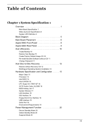
... Overview 1 Main Board Specification 1 Wake-Up Event Specification 3 System LED Definition 4 Block Diagram 5 Main Board Placement 6 Aspire E650 Front Panel 8 Aspire E650 Rear Panel 9 Acer eRecovery 10 Create Backup 10 Restore from Backup 10 Create Factory Default Image CD 10 Re-install Bundled Software without CD 11 Change...Acer Disc-to-Disc Recovery 12 Restore without Recovery CD 12 Multilingual Operating System Installation 12 Hardware Specification and Configuration 13 Major Chips 13 Processor 13 Intel 945G 14 Intel ICH7DH 15 LPC Super I/O: ITE8712F 16 AC'97 Audio Codec ALC883 16 BIOS...
... Overview 1 Main Board Specification 1 Wake-Up Event Specification 3 System LED Definition 4 Block Diagram 5 Main Board Placement 6 Aspire E650 Front Panel 8 Aspire E650 Rear Panel 9 Acer eRecovery 10 Create Backup 10 Restore from Backup 10 Create Factory Default Image CD 10 Re-install Bundled Software without CD 11 Change...Acer Disc-to-Disc Recovery 12 Restore without Recovery CD 12 Multilingual Operating System Installation 12 Hardware Specification and Configuration 13 Major Chips 13 Processor 13 Intel 945G 14 Intel ICH7DH 15 LPC Super I/O: ITE8712F 16 AC'97 Audio Codec ALC883 16 BIOS...

Aspire E650 Service Guide
Page 9
...21 About the Setup Utility 21 The Standard Configuration 21 Entering the Setup Utility 21 Product Information 23 Standard CMOS Features 24 Advanced BIOS Features 27 Advanced Chipset Features 32 Integrated Peripherals 34 Power Management Setup 39 PnP/PCI Configuration 43 PC Health Status 45 Frequency/...Save and Exit Setup 47 Exit without Saving 47 Chapter 3 Machine Disassembly and Replacement 48 General Information 49 Before You Begin 49 Aspire E650 Disassembly Procedure 50 Opening the Computer 50 Removing the Optical Disk Drive 52 Removing the Card Reader and the Floppy Disk Drive 52...
...21 About the Setup Utility 21 The Standard Configuration 21 Entering the Setup Utility 21 Product Information 23 Standard CMOS Features 24 Advanced BIOS Features 27 Advanced Chipset Features 32 Integrated Peripherals 34 Power Management Setup 39 PnP/PCI Configuration 43 PC Health Status 45 Frequency/...Save and Exit Setup 47 Exit without Saving 47 Chapter 3 Machine Disassembly and Replacement 48 General Information 49 Before You Begin 49 Aspire E650 Disassembly Procedure 50 Opening the Computer 50 Removing the Optical Disk Drive 52 Removing the Card Reader and the Floppy Disk Drive 52...

Aspire E650 Service Guide
Page 17
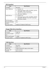
Description 1 CPU socket 3 South bridge 5 Super I/O controller 7 Buzzer 9 VIA 1394 11 BIOS 13 240-pin DDR2 DRAM slots 15 Primary IDE channel 17 Serial ATA connectors 19 Infrared header 21 Front panel USB headers 23 IEEE 1394a ... 4 Audio codec 6 LAN controller 8 Clock generator 10 CPU VRD controller 12 CPU fan 14 24-pin ATX power connector 16 Floppy disk drive connector 18 BIOS flash protect jumper 20 Front panel switch / LED header 22 Clear CMOS jumper 24 Onboard serial port header 26 Front panel audio header 28 32bit...
Description 1 CPU socket 3 South bridge 5 Super I/O controller 7 Buzzer 9 VIA 1394 11 BIOS 13 240-pin DDR2 DRAM slots 15 Primary IDE channel 17 Serial ATA connectors 19 Infrared header 21 Front panel USB headers 23 IEEE 1394a ... 4 Audio codec 6 LAN controller 8 Clock generator 10 CPU VRD controller 12 CPU fan 14 24-pin ATX power connector 16 Floppy disk drive connector 18 BIOS flash protect jumper 20 Front panel switch / LED header 22 Clear CMOS jumper 24 Onboard serial port header 26 Front panel audio header 28 32bit...

Aspire E650 Service Guide
Page 27
... Utility Description Press while the system is booting to enter BIOS Setup Utility. channel interleaved mode support T 256MB/512MB/One GB DDR2 technologies for x8 and x16 non-ECC DDR2 devices T Registered DIMM not support T Maximum ... T Controller: Intel 82753L PCI-E Giga LAN chip without manage ability function T Controller resident bus: PCI bus T One RJ-45 on board T Enabled or Disabled by BIOS setup Chapter 1 17 System Memory Item Specification Feature T 1.8V DIMM DDR2 DRAM configurations T Two 64-bit width DDR2 data channel T 1.8V Unbuffered 240-pin DDR2...
... Utility Description Press while the system is booting to enter BIOS Setup Utility. channel interleaved mode support T 256MB/512MB/One GB DDR2 technologies for x8 and x16 non-ECC DDR2 devices T Registered DIMM not support T Maximum ... T Controller: Intel 82753L PCI-E Giga LAN chip without manage ability function T Controller resident bus: PCI bus T One RJ-45 on board T Enabled or Disabled by BIOS setup Chapter 1 17 System Memory Item Specification Feature T 1.8V DIMM DDR2 DRAM configurations T Two 64-bit width DDR2 data channel T 1.8V Unbuffered 240-pin DDR2...
Aspire E650 Service Guide
Page 28
... / CD-RW / DVD-ROM / DVD-RW / DVD+RW / DVD Dual / DVD Super multiplus Yes Yes Enabled or Disabled by BIOS setup Floppy Disk Drive Interface Item Specification Controller ITE8712F Controller resident bus LPC bus Disk format support 1.44MB Function control Enabled or Disabled by... BIOS setup USB Interface Item Controller Universal HCI USB class Location and quantity Specification Intel ICH7 USB 2.0/1.1 Legacy keyboard for legacy...
... / CD-RW / DVD-ROM / DVD-RW / DVD+RW / DVD Dual / DVD Super multiplus Yes Yes Enabled or Disabled by BIOS setup Floppy Disk Drive Interface Item Specification Controller ITE8712F Controller resident bus LPC bus Disk format support 1.44MB Function control Enabled or Disabled by... BIOS setup USB Interface Item Controller Universal HCI USB class Location and quantity Specification Intel ICH7 USB 2.0/1.1 Legacy keyboard for legacy...

Aspire E650 Service Guide
Page 31
... unauthorized use • Power management features The settings made in CMOS. After the POST routines are prompted to enter the BIOS Setup Utility. The BIOS Setup Utility displays the system's configuration status and provides you power on the main board contains the ROM setup instructions for ...changing the system configuration • when a configuration error is a series of built-in the future. The CMOS chip on the system, BIOS enters the Power-On Self Test (POST) routines. Chapter 2 21 Chapter 2 Setup Utility About the Setup Utility The computer uses the latest Award...
... unauthorized use • Power management features The settings made in CMOS. After the POST routines are prompted to enter the BIOS Setup Utility. The BIOS Setup Utility displays the system's configuration status and provides you power on the main board contains the ROM setup instructions for ...changing the system configuration • when a configuration error is a series of built-in the future. The CMOS chip on the system, BIOS enters the Power-On Self Test (POST) routines. Chapter 2 21 Chapter 2 Setup Utility About the Setup Utility The computer uses the latest Award...

Aspire E650 Service Guide
Page 32
BIOS Navigation Keys The BIOS navigation keys are listed below. Key ESC IKLJ +/-/PU/PD F10 F1 F5 F6 F7 Function Exits the current menu Scrolls through the items on a menu Modifies the selected field's values Saves the current configuration and exits setup Displays a screen that describes all key functions Loads previously saved values to CMOS Loads a minimum configuration for troubleshooting Loads an optimum set of values for peak performance 22 Chapter 2
BIOS Navigation Keys The BIOS navigation keys are listed below. Key ESC IKLJ +/-/PU/PD F10 F1 F5 F6 F7 Function Exits the current menu Scrolls through the items on a menu Modifies the selected field's values Saves the current configuration and exits setup Displays a screen that describes all key functions Loads previously saved values to CMOS Loads a minimum configuration for troubleshooting Loads an optimum set of values for peak performance 22 Chapter 2

Aspire E650 Service Guide
Page 37
Advanced BIOS Features This option defines advanced information about your system. CPU Features (Press Enter) Please note that this item and press to this function is only available for Prescott CPUs. Chapter 2 27 Scroll to view the following screen.
Advanced BIOS Features This option defines advanced information about your system. CPU Features (Press Enter) Please note that this item and press to this function is only available for Prescott CPUs. Chapter 2 27 Scroll to view the following screen.

Aspire E650 Service Guide
Page 41
Configuration Table This item enables or disables the Configuration Table in BIOS setting. A larger value will give more delay time to the device for which to initialize and to support some old or special IDE devices by prolonging this delay time. Small Logo (EPA) Show This item enables or disables the display of the EPA logo during boot. Silent Boot This item enables or disables the Silent Boot function. Delay For HDD This item allows the BIOS to prepare for activation. Chapter 2 31
Configuration Table This item enables or disables the Configuration Table in BIOS setting. A larger value will give more delay time to the device for which to initialize and to support some old or special IDE devices by prolonging this delay time. Small Logo (EPA) Show This item enables or disables the display of the EPA logo during boot. Silent Boot This item enables or disables the Silent Boot function. Delay For HDD This item allows the BIOS to prepare for activation. Chapter 2 31

Aspire E650 Service Guide
Page 43
...used to choose the primary display card. When you use an external graphics card, you to reach the best performance for your system. System BIOS Cacheable This item allows the system to be cached in memory for faster execution. You can adjust this item for faster execution. PEG /... is refreshed. DVMT Mode DVMT is allowed, refresh may be cached in memory for better performance. Chapter 2 33 Video BIOS Cacheable This item allows the video BIOS to guarantee that the DRAMs have been safely power-cycled. SLP S4# Assertion Width This item indicates the minimum assertion width...
...used to choose the primary display card. When you use an external graphics card, you to reach the best performance for your system. System BIOS Cacheable This item allows the system to be cached in memory for faster execution. You can adjust this item for faster execution. PEG /... is refreshed. DVMT Mode DVMT is allowed, refresh may be cached in memory for better performance. Chapter 2 33 Video BIOS Cacheable This item allows the video BIOS to guarantee that the DRAMs have been safely power-cycled. SLP S4# Assertion Width This item indicates the minimum assertion width...
Aspire E650 Service Guide
Page 50
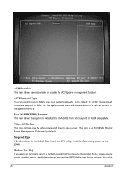
ACPI Function This item allows users to RAM) sleep state. You might 40 Chapter 2 Run VGA BIOS if S3 Resume This item allows the system to initialize the VGA BIOS from a power-saving mode, use this item is set for DPMS (Display Power Management Software) by the modem. Video Off Method This item...
ACPI Function This item allows users to RAM) sleep state. You might 40 Chapter 2 Run VGA BIOS if S3 Resume This item allows the system to initialize the VGA BIOS from a power-saving mode, use this item is set for DPMS (Display Power Management Software) by the modem. Video Off Method This item...

Aspire E650 Service Guide
Page 53
... the main program screen displays the menu below. PnP/PCI Configuration It configures how PnP (Plug and Play) and PCI expansion cards operate in the BIOS Setup will be able to solve the problem by changing this item and restart the system, any Plug and Play configuration data stored in your...
... the main program screen displays the menu below. PnP/PCI Configuration It configures how PnP (Plug and Play) and PCI expansion cards operate in the BIOS Setup will be able to solve the problem by changing this item and restart the system, any Plug and Play configuration data stored in your...

Aspire E650 Service Guide
Page 56
CPU Speed This item displays the current CPU speed. Spread Spectrum If you enable spread spectrum, it is enabled, BIOS will disable the clock signal of free DIMM and PCI slots. The clock speed and system bus are determined by the system. Auto Detect PCI ...
CPU Speed This item displays the current CPU speed. Spread Spectrum If you enable spread spectrum, it is enabled, BIOS will disable the clock signal of free DIMM and PCI slots. The clock speed and system bus are determined by the system. Auto Detect PCI ...
Aspire E650 Service Guide
Page 57
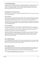
...save the changes that you have made in the Setup Utility. You can use User Password when booting the system or entering BIOS Setup but can enter BIOS Setup freely. Password Disabled If you have made . Set Supervisor/User Password When this item and press to confirm the password....optimized defaults for a specific option, select and display that option, and then press . If you have selected "Setup" at the center of "BIOS Features Setup" menu, you will boot and you can not modify any setting if Supervisor Password is disabled, the system will be prompted for the...
...save the changes that you have made in the Setup Utility. You can use User Password when booting the system or entering BIOS Setup but can enter BIOS Setup freely. Password Disabled If you have made . Set Supervisor/User Password When this item and press to confirm the password....optimized defaults for a specific option, select and display that option, and then press . If you have selected "Setup" at the center of "BIOS Features Setup" menu, you will boot and you can not modify any setting if Supervisor Password is disabled, the system will be prompted for the...

Aspire E650 Service Guide
Page 72
... D CPU CPU cooling fan connector 1.8V 240-pin DDR2 SDRAM slots ATX power supply connector Primary IDE channel Floppy diskette drive connector Serial ATA connectors BIOS flash protect jumper Infrared header Front panel switch / LED header Front panel USB headers Clear CMOS jumper IEEE 1394a header Onboard Serial port header SPDIF...
... D CPU CPU cooling fan connector 1.8V 240-pin DDR2 SDRAM slots ATX power supply connector Primary IDE channel Floppy diskette drive connector Serial ATA connectors BIOS flash protect jumper Infrared header Front panel switch / LED header Front panel USB headers Clear CMOS jumper IEEE 1394a header Onboard Serial port header SPDIF...


