Aspire 9500 User's Guide
Page 90
...rated 7 A 125 V minimum, VDE approved or its equivalent. There may present a risk of electric shock from the wall outlet before serving or disassembling this product yourself, as the product's battery we recommend in the product specification list. b If liquid has been spilled into this product from children...conditions: a When the power cord or plug is damaged or frayed. Never spill liquid of any kind into the product. Do not disassemble or dispose of power supply cord set (provided in your accessories box) for service. 12 The notebook PC series uses lithium batteries. ...
...rated 7 A 125 V minimum, VDE approved or its equivalent. There may present a risk of electric shock from the wall outlet before serving or disassembling this product yourself, as the product's battery we recommend in the product specification list. b If liquid has been spilled into this product from children...conditions: a When the power cord or plug is damaged or frayed. Never spill liquid of any kind into the product. Do not disassemble or dispose of power supply cord set (provided in your accessories box) for service. 12 The notebook PC series uses lithium batteries. ...
Aspire 9500 User's Guide
Page 91
... and other intellectual property rights. U.S. English English 81 Laser compliance statement The CD or DVD drive used with high-precision manufacturing techniques. Reverse engineering or disassembly is produced with this copyright protection technology must be authorized by U.S. Patent Nos. 4,631,603; 4,819,098; 4,907,093; 5,315,448; VARNING: LASERSTRÅLNING...
... and other intellectual property rights. U.S. English English 81 Laser compliance statement The CD or DVD drive used with high-precision manufacturing techniques. Reverse engineering or disassembly is produced with this copyright protection technology must be authorized by U.S. Patent Nos. 4,631,603; 4,819,098; 4,907,093; 5,315,448; VARNING: LASERSTRÅLNING...
Service Guide
Page 6
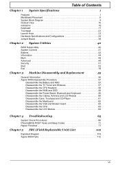
... Security 51 Boot 52 Exit 53 Chapter 3 Machine Disassembly and Replacement 55 General Information 56 Aspire 9500 Disassembly Procedure 57 Disassemble the Battery and HDD 57 Disassemble the TV Tuner and Wireless 57 Disassemble the CPU Heatsink 58 Disassemble the RAM and ODD 58 Disassemble the Power Board, Bluetooth and Keyboard 59 Disassemble the Cables, Antenna and LCD Module 60...
... Security 51 Boot 52 Exit 53 Chapter 3 Machine Disassembly and Replacement 55 General Information 56 Aspire 9500 Disassembly Procedure 57 Disassemble the Battery and HDD 57 Disassemble the TV Tuner and Wireless 57 Disassemble the CPU Heatsink 58 Disassemble the RAM and ODD 58 Disassemble the Power Board, Bluetooth and Keyboard 59 Disassemble the Cables, Antenna and LCD Module 60...

Service Guide
Page 60
... 3 Aspire 9500 When you need the following tools: T Wrist grounding strap and conductive mat for preventing electrostatic discharge T small phillips screwdriver T flat head screwdriver T Phillips screwdriver T Hex screwdriver NOTE: The screws for maintenance and troubleshooting. Machine Disassembly and Replacement... Chapter 3 This chapter contains step-by-step procedures on how to avoid mismatch when putting back the components. To disassemble the computer, you remove the stripe cover, please...
... 3 Aspire 9500 When you need the following tools: T Wrist grounding strap and conductive mat for preventing electrostatic discharge T small phillips screwdriver T flat head screwdriver T Phillips screwdriver T Hex screwdriver NOTE: The screws for maintenance and troubleshooting. Machine Disassembly and Replacement... Chapter 3 This chapter contains step-by-step procedures on how to avoid mismatch when putting back the components. To disassemble the computer, you remove the stripe cover, please...
Service Guide
Page 61
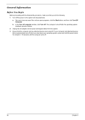
... hold the power button for at least 8 ~10 seconds until the computer turns off. 56 Chapter 3 General Information Before You Begin Before proceeding with the disassembly procedure, make sure that the computer and any open programs, click the Start button, and then click Turn Off Computer. a. Save and close any open...
... hold the power button for at least 8 ~10 seconds until the computer turns off. 56 Chapter 3 General Information Before You Begin Before proceeding with the disassembly procedure, make sure that the computer and any open programs, click the Start button, and then click Turn Off Computer. a. Save and close any open...
Service Guide
Page 62
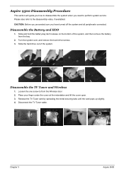
...hard drive screws. 3. Place your finger under the cover at the indentation and lift the cover open. 3. Aspire 9500 Disassembly Procedure This section will guide you how to disassemble the system when you have turned off the system and all peripherals connected. Slide the hard drive out of the...the battery from the Wireless door 2. Loosen the one screw to from the bay. 2. Chapter 3 Aspire 9500 Slide and hold the battery-bay latch release on the bottom of the system. Disassemble the Battery and HDD 1. Disconnect the TV Tuner cable. CAUTION: Before you proceeded sure you need...
...hard drive screws. 3. Place your finger under the cover at the indentation and lift the cover open. 3. Aspire 9500 Disassembly Procedure This section will guide you how to disassemble the system when you have turned off the system and all peripherals connected. Slide the hard drive out of the...the battery from the Wireless door 2. Loosen the one screw to from the bay. 2. Chapter 3 Aspire 9500 Slide and hold the battery-bay latch release on the bottom of the system. Disassemble the Battery and HDD 1. Disconnect the TV Tuner cable. CAUTION: Before you proceeded sure you need...

Service Guide
Page 63
...tabs until the module pops up slightly. 8. Remove the two screws and detach the door. 2. Tear the tape before you conduct the next step. 6. Disassemble the CPU Heatsink 1. Remove the three screws to release the RAM door. 2. Remove the one screw to detach the CPU fan. 3. Disconnect the antenna ...cables from the Mini PCI card. 7. Disassemble the RAM and ODD 1. Use your fingertips to carefully spread apart the securing clips on each end of its connector. Lift the Mini PCI card...
...tabs until the module pops up slightly. 8. Remove the two screws and detach the door. 2. Tear the tape before you conduct the next step. 6. Disassemble the CPU Heatsink 1. Remove the three screws to release the RAM door. 2. Remove the one screw to detach the CPU fan. 3. Disconnect the antenna ...cables from the Mini PCI card. 7. Disassemble the RAM and ODD 1. Use your fingertips to carefully spread apart the securing clips on each end of its connector. Lift the Mini PCI card...

Service Guide
Page 64
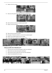
4. Then pull the ODD out from the routing channels with the tapes following system board. 5. Disassemble the Power Board, Bluetooth and Keyboard 1. Chapter 3 Aspire 9500 Disconnect the bluetooth cable from the system. 7. Before you detach the bluetooth, you have to lift the hinge cover on the right side. 2. Remove the ...
4. Then pull the ODD out from the routing channels with the tapes following system board. 5. Disassemble the Power Board, Bluetooth and Keyboard 1. Chapter 3 Aspire 9500 Disconnect the bluetooth cable from the system. 7. Before you detach the bluetooth, you have to lift the hinge cover on the right side. 2. Remove the ...
Service Guide
Page 65
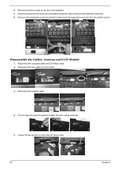
... side as shown here. 60 Chapter 3 6. Disconnect the touchpad cable and CD-Player cable. 2. Tear the tape then pull the antenna cables from the board. 3. Disassemble the Cables, Antenna and LCD Module 1. Disconnect the Antenna cable. 4. Loosen the two screws on the keyboard connector pull-tab to the keyboard connector. 8. Disconnect...
... side as shown here. 60 Chapter 3 6. Disconnect the touchpad cable and CD-Player cable. 2. Tear the tape then pull the antenna cables from the board. 3. Disassemble the Cables, Antenna and LCD Module 1. Disconnect the Antenna cable. 4. Loosen the two screws on the keyboard connector pull-tab to the keyboard connector. 8. Disconnect...
Service Guide
Page 66
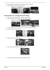
... as shown. 3. Remove the two screws securing the touchpad board support. Disassemble Case, Touchpad and CD-Player 1. Remove those five screws located on the upper case as shown. 2. Turn the system over and loosen the five screws from here. 6. Chapter 3 Aspire 9500 cable from the edge of the rear side. 7. Tear the tape...
... as shown. 3. Remove the two screws securing the touchpad board support. Disassemble Case, Touchpad and CD-Player 1. Remove those five screws located on the upper case as shown. 2. Turn the system over and loosen the five screws from here. 6. Chapter 3 Aspire 9500 cable from the edge of the rear side. 7. Tear the tape...
Service Guide
Page 67
... from the position. 12. Be aware of the mainboard. 4. Detach the touchpad support from the system. Gently detach the touchpad board from the system. 15. Disassemble the Mainboard 1. Disconnect the power board cable from the rear of indention positions to unhook the touchpad support. 14. 8. Remove the six henx screws from...
... from the position. 12. Be aware of the mainboard. 4. Detach the touchpad support from the system. Gently detach the touchpad board from the system. 15. Disassemble the Mainboard 1. Disconnect the power board cable from the rear of indention positions to unhook the touchpad support. 14. 8. Remove the six henx screws from...
Service Guide
Page 68
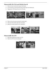
Remove the one screw securing the modem board. 5. Chapter 3 Aspire 9500 Disassemble the VGA and Modem board 1. With a flat screwdriver to loosen the CPU. 2. Remove the two screws securing the VGA board. 2. Detach the modem board from the VGA board. 4. Separate the VGA thermal from the mainboard. Disconnect the modem cable from the VGA thermal. 3. Disassemble the CPU 1. Trun the VGA over and loosen the three screws from the position. 6. Detach the CPU from the mainboard.
Remove the one screw securing the modem board. 5. Chapter 3 Aspire 9500 Disassemble the VGA and Modem board 1. With a flat screwdriver to loosen the CPU. 2. Remove the two screws securing the VGA board. 2. Detach the modem board from the VGA board. 4. Separate the VGA thermal from the mainboard. Disconnect the modem cable from the VGA thermal. 3. Disassemble the CPU 1. Trun the VGA over and loosen the three screws from the position. 6. Detach the CPU from the mainboard.
Service Guide
Page 69
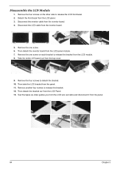
... Chapter 3 Remove the one screw. 6. Disconnect the invertor cable from the LCD module. 8. Remove the four screws to release the bracket from the invertor board. 4. Disassemble the LCD Module 1. Then take the LCD bracket from the panel. 11.
... Chapter 3 Remove the one screw. 6. Disconnect the invertor cable from the LCD module. 8. Remove the four screws to release the bracket from the invertor board. 4. Disassemble the LCD Module 1. Then take the LCD bracket from the panel. 11.
Service Guide
Page 75
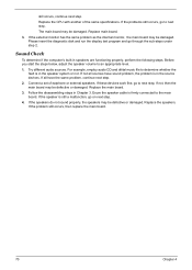
..., continue next step. 2. If the speakers do not sound properly, the speakers may be defective or damaged. Connect a set of the same specifications. Follow the disassembling steps in speakers are functioning properly, perform the following steps. If not all have sound problem, the problem is firmly connected to next step. still...
..., continue next step. 2. If the speakers do not sound properly, the speakers may be defective or damaged. Connect a set of the same specifications. Follow the disassembling steps in speakers are functioning properly, perform the following steps. If not all have sound problem, the problem is firmly connected to next step. still...


