Aspire 7560, 7560G Service Guide
Page 6
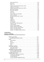
... Card 1-38 Audio Codec and Amplifier 1-39 Audio Interface 1-39 Wireless Module 802.11b/g/n 1-40 Battery 1-40 VRAM 1-40 USB Port 1-40 HDMI Port 1-41 AC Adapter 1-41 System Power Management 1-41 Card Reader 1-42 System LED Indicator 1-42 System DMA Specification 1-43 System Interrupt Specification 1-44 System IO Address Map 1-45...
... Card 1-38 Audio Codec and Amplifier 1-39 Audio Interface 1-39 Wireless Module 802.11b/g/n 1-40 Battery 1-40 VRAM 1-40 USB Port 1-40 HDMI Port 1-41 AC Adapter 1-41 System Power Management 1-41 Card Reader 1-42 System LED Indicator 1-42 System DMA Specification 1-43 System Interrupt Specification 1-44 System IO Address Map 1-45...
Aspire 7560, 7560G Service Guide
Page 18
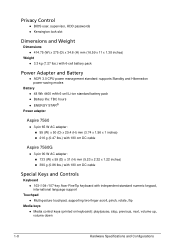
...48 Wh 4400 mAh 6-cell Li-ion standard battery pack Battery life: TBC hours ENERGY STAR® Power adapter Aspire 7560 0 3-pin 65 W AC adapter: 95 (W) x 50 (D) x 25.4 (H) mm (3.74 x 1.96 x 1 inches) 216 g (0.47 lbs...0 3-pin 90 W AC adapter: 133 (W) x 59 (D) x 31 (H) mm (5.23 x 2.32 x 1.22 inches) 390 g (0.86 lbs.) with 180 cm DC cable Special Keys and Controls 0 Keyboard 103-/104-/107-key Acer FineTip keyboard with independent standard numeric ...
...48 Wh 4400 mAh 6-cell Li-ion standard battery pack Battery life: TBC hours ENERGY STAR® Power adapter Aspire 7560 0 3-pin 65 W AC adapter: 95 (W) x 50 (D) x 25.4 (H) mm (3.74 x 1.96 x 1 inches) 216 g (0.47 lbs...0 3-pin 90 W AC adapter: 133 (W) x 59 (D) x 31 (H) mm (5.23 x 2.32 x 1.22 inches) 390 g (0.86 lbs.) with 180 cm DC cable Special Keys and Controls 0 Keyboard 103-/104-/107-key Acer FineTip keyboard with independent standard numeric ...
Aspire 7560, 7560G Service Guide
Page 19
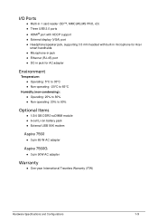
.../speaker jack, supporting 3.5 mm headset with built-in microphone for Acer smart handhelds Microphone-in jack Ethernet (RJ-45) port DC-in jack for AC adapter Environment 0 Temperature: Operating: 5°C to 35°... 6-cell Li-ion battery pack External USB 56K modem Aspire 7560 0 3-pin 65 W AC adapter Aspire 7560G 0 3-pin 90W AC adapter Warranty 0 One-year International Travelers Warranty (ITW) Hardware Specifications and Configurations 1-9
.../speaker jack, supporting 3.5 mm headset with built-in microphone for Acer smart handhelds Microphone-in jack Ethernet (RJ-45) port DC-in jack for AC adapter Environment 0 Temperature: Operating: 5°C to 35°... 6-cell Li-ion battery pack External USB 56K modem Aspire 7560 0 3-pin 65 W AC adapter Aspire 7560G 0 3-pin 90W AC adapter Warranty 0 One-year International Travelers Warranty (ITW) Hardware Specifications and Configurations 1-9
Aspire 7560, 7560G Service Guide
Page 27
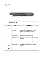
... when the computer is turned off . 6 Ethernet (RJ-45) port Connects to an Ethernet 10/100/1000-based network. 7 DC-in jack Connects to an AC adapter.
... when the computer is turned off . 6 Ethernet (RJ-45) port Connects to an Ethernet 10/100/1000-based network. 7 DC-in jack Connects to an AC adapter.
Aspire 7560, 7560G Service Guide
Page 51
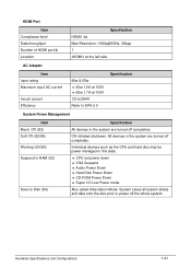
... Item Compliance level Data throughput Number of HDMI port(s) Location Specification HDMI1.4a Max Resolution: 1080p@60Hz, 36bpp 1 JHDMI1 at the left side AC Adapter Item Input rating Maximum input AC current Inrush current Efficiency 90w & 65w 90w:1.5A at 100V 65w:1.7A at 100V 12t at 264V Refer to Disk...
... Item Compliance level Data throughput Number of HDMI port(s) Location Specification HDMI1.4a Max Resolution: 1080p@60Hz, 36bpp 1 JHDMI1 at the left side AC Adapter Item Input rating Maximum input AC current Inrush current Efficiency 90w & 65w 90w:1.5A at 100V 65w:1.7A at 100V 12t at 264V Refer to Disk...
Aspire 7560, 7560G Service Guide
Page 76
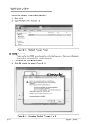
WinFlash Utility 0 Perform the following to device before executing program. 3. Make sure AC adapter is connecting to use the WinFlash Utility: 1. Click OK to OS. 2. Double click the WinFlash executable. 4. Boot to begin the update. (Figure 2-19) 2-18 Figure 2-19. Winflash Program Folder NOTE: NOTE: Flashing of 2) System Utilities Executing Winflash Program (1 of system BIOS cannot be performed on battery power. Open Winflash folder. (Figure 2-18) Figure 2-18.
WinFlash Utility 0 Perform the following to device before executing program. 3. Make sure AC adapter is connecting to use the WinFlash Utility: 1. Click OK to OS. 2. Double click the WinFlash executable. 4. Boot to begin the update. (Figure 2-19) 2-18 Figure 2-19. Winflash Program Folder NOTE: NOTE: Flashing of 2) System Utilities Executing Winflash Program (1 of system BIOS cannot be performed on battery power. Open Winflash folder. (Figure 2-18) Figure 2-18.
Aspire 7560, 7560G Service Guide
Page 77
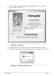
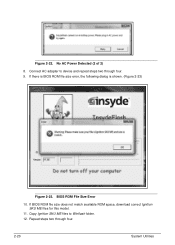
5. If the AC adapter is connected and there is no BIOS ROM file size error, a progress screen is not connected, the following dialogs are shown. (Figure 2-21, Figure 2-22) Figure 2-21. No AC Power Detected (1 of 2) System Utilities 2-19 If AC adapter is shown. (Figure 2-20) PXXX5 V0.08 PXXX5 V 1.00 Figure 2-20. InsydeFlash 6. After flashing process is complete, the program will automatically restart the system. 7.
5. If the AC adapter is connected and there is no BIOS ROM file size error, a progress screen is not connected, the following dialogs are shown. (Figure 2-21, Figure 2-22) Figure 2-21. No AC Power Detected (1 of 2) System Utilities 2-19 If AC adapter is shown. (Figure 2-20) PXXX5 V0.08 PXXX5 V 1.00 Figure 2-20. InsydeFlash 6. After flashing process is complete, the program will automatically restart the system. 7.
Aspire 7560, 7560G Service Guide
Page 78
Connect AC adapter to Winflash folder. 12. Copy Ignition SKU ME files to device and repeat steps two through four. 2-20 System Utilities If there is BIOS ROM file size error, the following dialog is shown. (Figure 2-23) Figure 2-23. Figure 2-22. BIOS ROM File Size Error 10. Repeat steps two through four. 9. If BIOS ROM file size does not match available ROM space, download correct Ignition SKU ME files for this model. 11. No AC Power Detected (2 of 2) 8.
Connect AC adapter to Winflash folder. 12. Copy Ignition SKU ME files to device and repeat steps two through four. 2-20 System Utilities If there is BIOS ROM file size error, the following dialog is shown. (Figure 2-23) Figure 2-23. Figure 2-22. BIOS ROM File Size Error 10. Repeat steps two through four. 9. If BIOS ROM file size does not match available ROM space, download correct Ignition SKU ME files for this model. 11. No AC Power Detected (2 of 2) 8.
Aspire 7560, 7560G Service Guide
Page 81
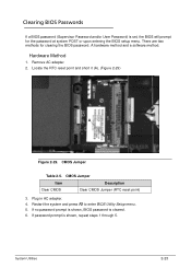
... Jumper Item Description Clear CMOS Clear CMOS Jumper (RTC reset point) 3. Plug in AC adapter. 4. Restart the system and press F2 to enter BIOS Utility Setup menu. 5. If password prompt is cleared. 6. System Utilities 2-23 There are two methods for ...
... Jumper Item Description Clear CMOS Clear CMOS Jumper (RTC reset point) 3. Plug in AC adapter. 4. Restart the system and press F2 to enter BIOS Utility Setup menu. 5. If password prompt is cleared. 6. System Utilities 2-23 There are two methods for ...
Aspire 7560, 7560G Service Guide
Page 95
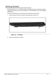
AC Adapter 2. Remove all cables from the system and peripherals. (Figure 3-2) A Figure 3-2. Observe the order of the sequence to avoid damage to performing any of the hardware components. Machine Maintenance Procedures 3-7 Remove power (A) from system. Perform the following prior to any maintenance procedures: 1. Getting Started 0 The flowchart (Figure 3-1) identifies sections illustrating the entire removal and install sequence.
AC Adapter 2. Remove all cables from the system and peripherals. (Figure 3-2) A Figure 3-2. Observe the order of the sequence to avoid damage to performing any of the hardware components. Machine Maintenance Procedures 3-7 Remove power (A) from system. Perform the following prior to any maintenance procedures: 1. Getting Started 0 The flowchart (Figure 3-1) identifies sections illustrating the entire removal and install sequence.
Aspire 7560, 7560G Service Guide
Page 199
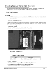
...Acer Aspire 7560/7560G. Locate the RTC reset point and short it (A). (Figure 5-3) A Figure 5-3. Clearing BIOS Password 0 If a BIOS password (Supervisor Password and/or User Password) is only for the password at system POST or upon entering the BIOS setup menu. Plug in AC adapter.... 4. Jumper and Connector Locations 5-5 Clearing Password 0 NOTE: NOTE: The following procedure: 1. If password prompt is cleared. 6. Remove AC adapter. 2. Clearing Password and BIOS Recovery 0 This section provides users ...
...Acer Aspire 7560/7560G. Locate the RTC reset point and short it (A). (Figure 5-3) A Figure 5-3. Clearing BIOS Password 0 If a BIOS password (Supervisor Password and/or User Password) is only for the password at system POST or upon entering the BIOS setup menu. Plug in AC adapter.... 4. Jumper and Connector Locations 5-5 Clearing Password 0 NOTE: NOTE: The following procedure: 1. If password prompt is cleared. 6. Remove AC adapter. 2. Clearing Password and BIOS Recovery 0 This section provides users ...
Aspire 7560, 7560G Service Guide
Page 200
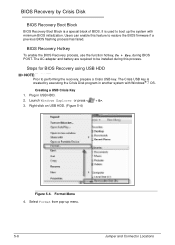
... 0 BIOS Recovery Boot Block is used to boot up menu. 5-6 Jumper and Connector Locations Launch Windows Explorer or press < + E>. 3. Users can enable this process. The AC adapter and battery are required to be installed during BIOS POST. Creating a USB Crisis Key 0 1. Right-click on USB HDD. (Figure 5-4) Figure 5-4. Steps for BIOS Recovery...
... 0 BIOS Recovery Boot Block is used to boot up menu. 5-6 Jumper and Connector Locations Launch Windows Explorer or press < + E>. 3. Users can enable this process. The AC adapter and battery are required to be installed during BIOS POST. Creating a USB Crisis Key 0 1. Right-click on USB HDD. (Figure 5-4) Figure 5-4. Steps for BIOS Recovery...
Aspire 7560, 7560G Service Guide
Page 203
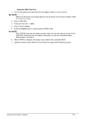
...BIOS. 7. Update the latest version BIOS for this machine by regular BIOS flashing process. Press the Power button to Getting Started. Disconnect the AC adapter and battery to Closed Front View. 2. Turn off , as shown on the USB HDD. Repeat steps 1 through 5. 6. Refer to reset... the embedded status. Using the USB Crisis Key 0 1. Plug in the AC adapter. 5. Press and hold . 4. Jumper and Connector Locations 5-9 NOTE: NOTE: Make sure the power and charge lights are off the system and disconnect...
...BIOS. 7. Update the latest version BIOS for this machine by regular BIOS flashing process. Press the Power button to Getting Started. Disconnect the AC adapter and battery to Closed Front View. 2. Turn off , as shown on the USB HDD. Repeat steps 1 through 5. 6. Refer to reset... the embedded status. Using the USB Crisis Key 0 1. Plug in the AC adapter. 5. Press and hold . 4. Jumper and Connector Locations 5-9 NOTE: NOTE: Make sure the power and charge lights are off the system and disconnect...


