Aspire 7230/7530/7530G Quick Guide
Page 11
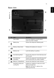
... the opening of the fan. 11 Base view English # Icon Item 1 Sub woofer 2 Battery bay Description Emits low frequency sound output. (only for certain models) Houses the computer's battery pack. 3 Battery release latch Releases the battery for removal. 4 Battery lock Locks the battery in position. 5 Hard disk bay-Main Houses the computer's hard disk (secured with...
... the opening of the fan. 11 Base view English # Icon Item 1 Sub woofer 2 Battery bay Description Emits low frequency sound output. (only for certain models) Houses the computer's battery pack. 3 Battery release latch Releases the battery for removal. 4 Battery lock Locks the battery in position. 5 Hard disk bay-Main Houses the computer's hard disk (secured with...
Aspire 7230/7530/7530G Quick Guide
Page 12
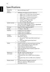
...* • AMD Athlon™ X2 dual-core processor* • Mobile AMD Sempron™ processor* • NVIDIA® nForce® MCP77MH • Acer InviLink™ 802.11b/g Dual-Channel DDR2 SDRAM support Up to 2 GB of DDR2 667 MHz memory, upgradeable to 4 GB using two soDIMM modules* Digital... microphone 402 (W) x 297 (D) x 41/43.9 (H) mm (15.83 x 11.69 x 1.61/1.73 inches) 3.90 kg (8.59 lbs.) with 2 HDDs and 8-cell battery pack* 3.80 kg (8.37 lbs.) with one HDD and 6-cell battery pack* Acer Bio-Protection fingerprint solution* BIOS user, supervisor, HDD passwords Kensington lock slot
...* • AMD Athlon™ X2 dual-core processor* • Mobile AMD Sempron™ processor* • NVIDIA® nForce® MCP77MH • Acer InviLink™ 802.11b/g Dual-Channel DDR2 SDRAM support Up to 2 GB of DDR2 667 MHz memory, upgradeable to 4 GB using two soDIMM modules* Digital... microphone 402 (W) x 297 (D) x 41/43.9 (H) mm (15.83 x 11.69 x 1.61/1.73 inches) 3.90 kg (8.59 lbs.) with 2 HDDs and 8-cell battery pack* 3.80 kg (8.37 lbs.) with one HDD and 6-cell battery pack* Acer Bio-Protection fingerprint solution* BIOS user, supervisor, HDD passwords Kensington lock slot
Aspire 7230/7530/7530G Service Guide
Page 7
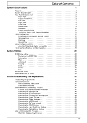
...12 Lock Keys and embedded numeric keypad 12 Windows Keys 13 Hot Keys 14 Special Key 15 Using the System Utilities 16 Acer GridVista (dual-display compatible 16 Hardware Specifications and Configurations 18 System Utilities 29 BIOS Setup Utility 29 Navigating the BIOS Utility ...General Information 46 Pre-disassembly Instructions 46 Disassembly Process 46 External Module Disassembly Process 47 External Modules Disassembly Flowchart 47 Removing the Battery Pack 48 Removing the SD dummy card 48 Removing the ExpressCard dummy card 49 Removing the Lower Covers 50 Removing the DIMM...
...12 Lock Keys and embedded numeric keypad 12 Windows Keys 13 Hot Keys 14 Special Key 15 Using the System Utilities 16 Acer GridVista (dual-display compatible 16 Hardware Specifications and Configurations 18 System Utilities 29 BIOS Setup Utility 29 Navigating the BIOS Utility ...General Information 46 Pre-disassembly Instructions 46 Disassembly Process 46 External Module Disassembly Process 47 External Modules Disassembly Flowchart 47 Removing the Battery Pack 48 Removing the SD dummy card 48 Removing the ExpressCard dummy card 49 Removing the Lower Covers 50 Removing the DIMM...
Aspire 7230/7530/7530G Service Guide
Page 9
Table of Contents Replacing the SD Dummy Tray 128 Replacing the Battery 128 Troubleshooting 129 Common Problems 129 Power On Issue 130 No Display Issue 131 Random Loss of BIOS Settings 132 LCD Failure 133 Built-In ... Clearing Password Check 159 BIOS Recovery by Crisis Disk 160 FRU (Field Replaceable Unit) List 161 Aspire 7230/7530/7530G Exploded Diagram 162 Aspire 7230/7530/7530G FRU List 163 Screw List 171 Model Definition and Configuration 172 Aspire 7230/7530/7530G Series 172 Test Compatible Components 189 Microsoft® Windows® Vista Environment Test 190...
Table of Contents Replacing the SD Dummy Tray 128 Replacing the Battery 128 Troubleshooting 129 Common Problems 129 Power On Issue 130 No Display Issue 131 Random Loss of BIOS Settings 132 LCD Failure 133 Built-In ... Clearing Password Check 159 BIOS Recovery by Crisis Disk 160 FRU (Field Replaceable Unit) List 161 Aspire 7230/7530/7530G Exploded Diagram 162 Aspire 7230/7530/7530G FRU List 163 Screw List 171 Model Definition and Configuration 172 Aspire 7230/7530/7530G Series 172 Test Compatible Components 189 Microsoft® Windows® Vista Environment Test 190...
Aspire 7230/7530/7530G Service Guide
Page 12
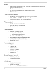
... x 11.69 x 1.61/1.73 inches) • 3.90 kg (8.59 lbs.) with 2 HDDs and 8-cell battery pack* • 3.80 kg (8.37 lbs.) with two built-in stereo speakers and one HDD and 6-cell battery pack* Privacy control • Acer Bio-Protection fingerprint solution* • BIOS user, supervisor, HDD passwords • Kensington lock slot Communication...
... x 11.69 x 1.61/1.73 inches) • 3.90 kg (8.59 lbs.) with 2 HDDs and 8-cell battery pack* • 3.80 kg (8.37 lbs.) with two built-in stereo speakers and one HDD and 6-cell battery pack* Privacy control • Acer Bio-Protection fingerprint solution* • BIOS user, supervisor, HDD passwords • Kensington lock slot Communication...

Aspire 7230/7530/7530G Service Guide
Page 19
Hard disk baySecondary Houses the computer's hard disk (secured with screws). Only for certain models). Locks the battery in position. Memory compartment Houses the computer's main memory. Hard disk bay-Main Houses the computer's hard disk (secured with... screws). Note: Do not cover or obstruct the opening of the fan. Chapter 1 9 Houses the computer's battery pack. Bottom View No. 1 2 3 4 5 6 7 8 Icon Item Subwoofer Battery bay Description Emits low frequency sound output (only for certain models. Ventilation slots and cooling fan Enable the computer to ...
Hard disk baySecondary Houses the computer's hard disk (secured with screws). Only for certain models). Locks the battery in position. Memory compartment Houses the computer's main memory. Hard disk bay-Main Houses the computer's hard disk (secured with... screws). Note: Do not cover or obstruct the opening of the fan. Chapter 1 9 Houses the computer's battery pack. Bottom View No. 1 2 3 4 5 6 7 8 Icon Item Subwoofer Battery bay Description Emits low frequency sound output (only for certain models. Ventilation slots and cooling fan Enable the computer to ...
Aspire 7230/7530/7530G Service Guide
Page 20
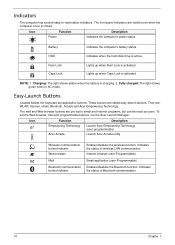
... programs, but can be reset by users. The front panel indicators are : WLAN, Internet, email, Bluetooth, Arcade and Acer Empowering Technology. Icon Function Power Description Indicates the computer's power status. Battery Indicates the computer's battery status. They are visible even when the computer cover is closed. Internet browser (user-Programmable) Email application (user...
... programs, but can be reset by users. The front panel indicators are : WLAN, Internet, email, Bluetooth, Arcade and Acer Empowering Technology. Icon Function Power Description Indicates the computer's power status. Battery Indicates the computer's battery status. They are visible even when the computer cover is closed. Internet browser (user-Programmable) Email application (user...
Aspire 7230/7530/7530G Service Guide
Page 29
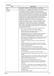
...processor1. Paired with dedicated controller for other standard peripheral functions. Unified Shader model 4.0 for notebooks that increases performance and typical battery life for geometry, vertex and pixel processor2. The MCP77M master feature set including a second generation PCI Express interface, industry ... power management processor, and other peripherals • AHCI SATA controller with support for full HD content decode and Playback with long battery life or with 836 balls and a 0.8 mm ball pitch. NVIDIA® Intellisample™ AA technology • Next generation ...
...processor1. Paired with dedicated controller for other standard peripheral functions. Unified Shader model 4.0 for notebooks that increases performance and typical battery life for geometry, vertex and pixel processor2. The MCP77M master feature set including a second generation PCI Express interface, industry ... power management processor, and other peripherals • AHCI SATA controller with support for full HD content decode and Playback with long battery life or with 836 balls and a 0.8 mm ball pitch. NVIDIA® Intellisample™ AA technology • Next generation ...
Aspire 7230/7530/7530G Service Guide
Page 38
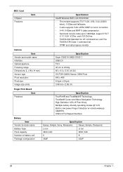
... Pixel 640 x 480 6.0µm x 6.0µm 3.98 (H) x 2.95 (V) Finger Print Board Features Item Battery Item Vendor & model name Battery Type Pack capacity Number of battery cell Package configuration Specification TruePrint® and TrueMatch® Technology. TrueNav® Cursor and Menu Navigation Technology High Definition... 128 x 8 Pixel Array Multiple battery-friendly operating modes @ 3.3V Built-in low power Finger Detection w/ remote wakeup capability USB 2.0 Full Speed Interface ...
... Pixel 640 x 480 6.0µm x 6.0µm 3.98 (H) x 2.95 (V) Finger Print Board Features Item Battery Item Vendor & model name Battery Type Pack capacity Number of battery cell Package configuration Specification TruePrint® and TrueMatch® Technology. TrueNav® Cursor and Menu Navigation Technology High Definition... 128 x 8 Pixel Array Multiple battery-friendly operating modes @ 3.3V Built-in low power Finger Detection w/ remote wakeup capability USB 2.0 Full Speed Interface ...
Aspire 7230/7530/7530G Service Guide
Page 51
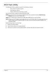
... required for the following conditions: • New versions of system programs • New features or options • Restore a BIOS when it becomes corrupted. If the battery pack does not contain enough power to run the Phlash utility. BIOS Flash Utility The BIOS flash memory update is not completely loaded.
... required for the following conditions: • New versions of system programs • New features or options • Restore a BIOS when it becomes corrupted. If the battery pack does not contain enough power to run the Phlash utility. BIOS Flash Utility The BIOS flash memory update is not completely loaded.
Aspire 7230/7530/7530G Service Guide
Page 56
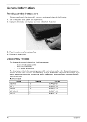
... module disassembly • Main unit disassembly • LCD module disassembly The flowcharts provided in the succeeding disassembly sections illustrate the entire disassembly sequence. Remove the battery pack. Disassembly Process The disassembly process is divided into the following : 1. Main Screw List Screw Quantity Part No. Turn off the power to any of...
... module disassembly • Main unit disassembly • LCD module disassembly The flowcharts provided in the succeeding disassembly sections illustrate the entire disassembly sequence. Remove the battery pack. Disassembly Process The disassembly process is divided into the following : 1. Main Screw List Screw Quantity Part No. Turn off the power to any of...
Aspire 7230/7530/7530G Service Guide
Page 58
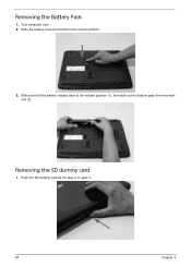
Slide the battery lock/unlock latch to eject it. 48 Chapter 3 Removing the Battery Pack 1. Push the SD dummy card all the way in to the unlock position. 3. Slide and hold the battery release latch to the release position (1), then slide out the battery pack from the main unit (2). 2 1 Removing the SD dummy card 1. Turn computer over. 2.
Slide the battery lock/unlock latch to eject it. 48 Chapter 3 Removing the Battery Pack 1. Push the SD dummy card all the way in to the unlock position. 3. Slide and hold the battery release latch to the release position (1), then slide out the battery pack from the main unit (2). 2 1 Removing the SD dummy card 1. Turn computer over. 2.
Aspire 7230/7530/7530G Service Guide
Page 60
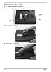
Carefully open the memory cover. See "Removing the Battery Pack" on page 48. 2. Loosen the ten captive screws from the Memory, HDD1, and HDD2 Covers. Remove the HDD1 cover as shown. 50 Chapter 3 Removing the Lower Covers 1. HDD1 Cover 3. Memory Cover HDD2 Cover 4.
Carefully open the memory cover. See "Removing the Battery Pack" on page 48. 2. Loosen the ten captive screws from the Memory, HDD1, and HDD2 Covers. Remove the HDD1 cover as shown. 50 Chapter 3 Removing the Lower Covers 1. HDD1 Cover 3. Memory Cover HDD2 Cover 4.
Aspire 7230/7530/7530G Service Guide
Page 61
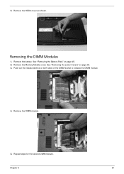
5. Remove the Memory Module cover. See "Removing the Lower Covers" on page 48. 2. Remove the DIMM module. 5. Remove the HDD2 cover as shown. Removing the DIMM Modules 1. Repeat steps for the second DIMM module. See "Removing the Battery Pack" on page 50. 3. Chapter 3 51 Push out the release latches on both sides of the DIMM socket to release the DIMM module. 4. Remove the battery.
5. Remove the Memory Module cover. See "Removing the Lower Covers" on page 48. 2. Remove the DIMM module. 5. Remove the HDD2 cover as shown. Removing the DIMM Modules 1. Repeat steps for the second DIMM module. See "Removing the Battery Pack" on page 50. 3. Chapter 3 51 Push out the release latches on both sides of the DIMM socket to release the DIMM module. 4. Remove the battery.
Aspire 7230/7530/7530G Service Guide
Page 62
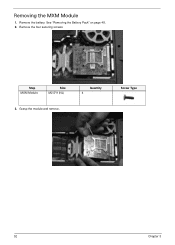
Step MXM Module Size M2.5*9 (NL) 3. Removing the MXM Module 1. Quantity 4 Screw Type 52 Chapter 3 Remove the battery. Remove the four securing screws. Grasp the module and remove. See "Removing the Battery Pack" on page 48. 2.
Step MXM Module Size M2.5*9 (NL) 3. Removing the MXM Module 1. Quantity 4 Screw Type 52 Chapter 3 Remove the battery. Remove the four securing screws. Grasp the module and remove. See "Removing the Battery Pack" on page 48. 2.
Aspire 7230/7530/7530G Service Guide
Page 63
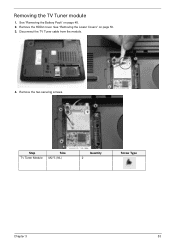
See "Removing the Lower Covers" on page 48. 2. Remove the HDD2 cover. Disconnect the TV Tuner cable from the module. 4. Remove the two securing screws. Step Tv Tuner Module Size M2*3 (NL) Quantity 2 Screw Type Chapter 3 53 Removing the TV Tuner module 1. See "Removing the Battery Pack" on page 50. 3.
See "Removing the Lower Covers" on page 48. 2. Remove the HDD2 cover. Disconnect the TV Tuner cable from the module. 4. Remove the two securing screws. Step Tv Tuner Module Size M2*3 (NL) Quantity 2 Screw Type Chapter 3 53 Removing the TV Tuner module 1. See "Removing the Battery Pack" on page 50. 3.
Aspire 7230/7530/7530G Service Guide
Page 64
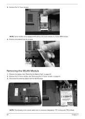
Removing the WLAN Module 1. NOTE: Some models come equipped with either a TV Tuner module or a Turbo RAM module. 6. Remove the battery. See "Removing the Battery Pack" on page 53. 3. 5. Remove the bracket from the WLAN board. NOTE: The following is the correct cable-color to connector designation: TR1 to Gray and TR2 to Black. 54 Chapter 3 Disconnect the antenna cables from the module. Remove the TV Tuner module. Remove the Tv Tuner module. See "Removing the TV Tuner module" on page 48. 2.
Removing the WLAN Module 1. NOTE: Some models come equipped with either a TV Tuner module or a Turbo RAM module. 6. Remove the battery. See "Removing the Battery Pack" on page 53. 3. 5. Remove the bracket from the WLAN board. NOTE: The following is the correct cable-color to connector designation: TR1 to Gray and TR2 to Black. 54 Chapter 3 Disconnect the antenna cables from the module. Remove the TV Tuner module. Remove the Tv Tuner module. See "Removing the TV Tuner module" on page 48. 2.
Aspire 7230/7530/7530G Service Guide
Page 66
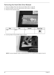
Use the pull-tab to lift up the HDD module to device, avoid pressing down on it or placing heavy objects on top of it. 56 Chapter 3 Screw Type NOTE: To prevent damage to remove. Removing the Hard Disk Drive Module 1. See "Removing the Battery Pack" on page 50. 3. Step HDD Size M2*3 Quantity 2 4. See "Removing the Lower Covers" on page 48. 2. Remove the HDD1 cover. Remove the two securing screws. Remove the Battery Pack.
Use the pull-tab to lift up the HDD module to device, avoid pressing down on it or placing heavy objects on top of it. 56 Chapter 3 Screw Type NOTE: To prevent damage to remove. Removing the Hard Disk Drive Module 1. See "Removing the Battery Pack" on page 50. 3. Step HDD Size M2*3 Quantity 2 4. See "Removing the Lower Covers" on page 48. 2. Remove the HDD1 cover. Remove the two securing screws. Remove the Battery Pack.
Aspire 7230/7530/7530G Service Guide
Page 68
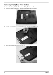
Loosen the captive screw securing the ODD module and remove the ODD cap. 3. Remove the Battery Pack. See "Removing the Battery Pack" on page 48. 2. Carefully use a screwdriver to push the locking catch and remove the ODD module. 4. Grasp the module and pull out from the main unit. 58 Chapter 3 Removing the Optical Drive Module 1.
Loosen the captive screw securing the ODD module and remove the ODD cap. 3. Remove the Battery Pack. See "Removing the Battery Pack" on page 48. 2. Carefully use a screwdriver to push the locking catch and remove the ODD module. 4. Grasp the module and pull out from the main unit. 58 Chapter 3 Removing the Optical Drive Module 1.
Aspire 7230/7530/7530G Service Guide
Page 72
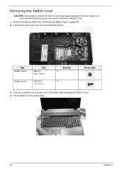
Turn the computer over and open the LCD module fully to remove the Switch Cover. 1. Remove the Battery Pack. Locate and remove the nine securing screws as shown. Lift the Switch Cover up and away. 62 Chapter 3 It is recommended that only fingers are used to expose the Switch Cover. 4. Removing the Switch Cover CAUTION: Using tools to remove the Switch Cover may cause damage to the outer casing. See "Removing the Battery Pack" on page 48. 2. Step Switch Cover Switch Cover Size M2.5*3 Blue Callout M2.5*6.5 Red Callout Quantity 4 5 Screw Type 3.
Turn the computer over and open the LCD module fully to remove the Switch Cover. 1. Remove the Battery Pack. Locate and remove the nine securing screws as shown. Lift the Switch Cover up and away. 62 Chapter 3 It is recommended that only fingers are used to expose the Switch Cover. 4. Removing the Switch Cover CAUTION: Using tools to remove the Switch Cover may cause damage to the outer casing. See "Removing the Battery Pack" on page 48. 2. Step Switch Cover Switch Cover Size M2.5*3 Blue Callout M2.5*6.5 Red Callout Quantity 4 5 Screw Type 3.


