
Quick Start Guide
Page 10
Note: Do not cover or obstruct the opening of the fan. 4 Battery bay Houses the computer's battery pack. 5 Battery release latch Releases the battery for removal. Houses the computer's main memory. Locks the battery in position. 3 Ventilation slots and Enable the computer to stay cool, even cooling fan after prolonged use. English 10 Base view 1 2 5 3 4 # Icon Item 1 Hard disk bay Memory compartment 2 Battery lock Description Houses the computer's hard disk (secured with screws).
Note: Do not cover or obstruct the opening of the fan. 4 Battery bay Houses the computer's battery pack. 5 Battery release latch Releases the battery for removal. Houses the computer's main memory. Locks the battery in position. 3 Ventilation slots and Enable the computer to stay cool, even cooling fan after prolonged use. English 10 Base view 1 2 5 3 4 # Icon Item 1 Hard disk bay Memory compartment 2 Battery lock Description Houses the computer's hard disk (secured with screws).

Service Guide
Page 20
Enable the computer to stay cool, even after prolonged use. Houses the computer's main memory. Note: Do not cover or obstruct the opening of the fan. Releases the battery for removal. 10 Chapter 1 Locks the battery in position. Houses the computer's battery pack. Bottom View 1 2 5 3 4 No. 1 2 3 4 5 Icon Item Hard disk bay Memory compartment Battery lock Ventilation slots and cooling fan Battery bay Battery release latch Description Houses the computer's hard disk (secured with screws).
Enable the computer to stay cool, even after prolonged use. Houses the computer's main memory. Note: Do not cover or obstruct the opening of the fan. Releases the battery for removal. 10 Chapter 1 Locks the battery in position. Houses the computer's battery pack. Bottom View 1 2 5 3 4 No. 1 2 3 4 5 Icon Item Hard disk bay Memory compartment Battery lock Ventilation slots and cooling fan Battery bay Battery release latch Description Houses the computer's hard disk (secured with screws).
Service Guide
Page 26
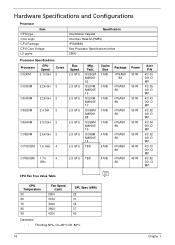
... rPGA98 8A rPGA98 8A rPGA98 8A rPGA98 8A rPGA98 8A rPGA98 8A rPGA98 8A rPGA98 8A Power 35 W 35 W 35 W 35 W 35 W 35 W 45 W 45 W Acer P/N KC.33 001.D MP KC.35 001.D MP KC.43 001.D MP KC.52 001.D MP KC.54 001.D MP KC.62 001.D MP KC....72 001.Q MP KC.82 001.Q MP CPU Fan True Value Table CPU Temperature 50 60 70 80 85 Fan Speed (rpm) 2800 3100 3400 3800 4200 SPL Spec (dBA) 28 31 34 37 40 Clarksfield • Throttling 50%: On...
... rPGA98 8A rPGA98 8A rPGA98 8A rPGA98 8A rPGA98 8A rPGA98 8A rPGA98 8A rPGA98 8A Power 35 W 35 W 35 W 35 W 35 W 35 W 45 W 45 W Acer P/N KC.33 001.D MP KC.35 001.D MP KC.43 001.D MP KC.52 001.D MP KC.54 001.D MP KC.62 001.D MP KC....72 001.Q MP KC.82 001.Q MP CPU Fan True Value Table CPU Temperature 50 60 70 80 85 Fan Speed (rpm) 2800 3100 3400 3800 4200 SPL Spec (dBA) 28 31 34 37 40 Clarksfield • Throttling 50%: On...

Service Guide
Page 106
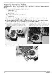
Remove the four securing screws (in reverse numerical order from screw 4 to the Mainboard (green callout). 4. Remove the single screw securing the Fan to screw 1) from the Mainboard. 3. Removing the Thermal Module 1. See "Removing the Mainboard" on page 91. 2. Disconnect the fan cable from the Thermal Module (red callout). 4 3 2 1 Step Thermal Module Size CPU_SCREW_SPRIN 5 Quantity Screw Type 94 Chapter 3
Remove the four securing screws (in reverse numerical order from screw 4 to the Mainboard (green callout). 4. Remove the single screw securing the Fan to screw 1) from the Mainboard. 3. Removing the Thermal Module 1. See "Removing the Mainboard" on page 91. 2. Disconnect the fan cable from the Thermal Module (red callout). 4 3 2 1 Step Thermal Module Size CPU_SCREW_SPRIN 5 Quantity Screw Type 94 Chapter 3
Service Guide
Page 110
Apply a small amount of thermal grease to the centre of the CPU-there is sufficient. 3. Connect the fan cable to spread the thermal grease evenly. 4. Remove all heat pads are approved for use : • Silmore GP50 • Honeywell PCM45F-SP • ShinEtsu 7762 ... pads are in place before replacing the Thermal Module. The following thermal grease types are approved for use : • Eapus XR-PE 1. Replace the single Fan screw and the four Thermal Module screws (in numerical order from the CPU using a lint-free cloth or cotton swab and Isopropyl Alcohol, Acetone, or...
Apply a small amount of thermal grease to the centre of the CPU-there is sufficient. 3. Connect the fan cable to spread the thermal grease evenly. 4. Remove all heat pads are approved for use : • Silmore GP50 • Honeywell PCM45F-SP • ShinEtsu 7762 ... pads are in place before replacing the Thermal Module. The following thermal grease types are approved for use : • Eapus XR-PE 1. Replace the single Fan screw and the four Thermal Module screws (in numerical order from the CPU using a lint-free cloth or cotton swab and Isopropyl Alcohol, Acetone, or...

Service Guide
Page 144
... (see "Online Support Information" on page 231. 132 Chapter 4 Check the power cable is still not resolved, see "Thermal Unit Failure" on page 144) and fan airways are not necessary to boot the computer to the failure point. 6. Remove any recently installed software. 7. Power On Issue If the system doesn't power...
... (see "Online Support Information" on page 231. 132 Chapter 4 Check the power cable is still not resolved, see "Thermal Unit Failure" on page 144) and fan airways are not necessary to boot the computer to the failure point. 6. Remove any recently installed software. 7. Power On Issue If the system doesn't power...
Service Guide
Page 145
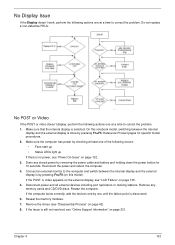
... 42). 8. Chapter 4 133 Do not replace a non-defective FRUs: No POST or Video If the POST or video doesn't display, perform the following occurs: • Fans start up • Status LEDs light up If there is no power, see "Online Support Information" on page 231. Make sure the computer has power...
... 42). 8. Chapter 4 133 Do not replace a non-defective FRUs: No POST or Video If the POST or video doesn't display, perform the following occurs: • Fans start up • Status LEDs light up If there is no power, see "Online Support Information" on page 231. Make sure the computer has power...
Service Guide
Page 156
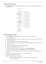
... Manager to verify mouse operation. No Connect it well CPU OK? Restart the computer. 6. If the issue is a good connection. No Replace fan CPU heat sink well seated? No Replace CPU Replace Mainboard External Mouse Failure If an external Mouse fails, perform the following actions one at a ...there is not fixed, repeat the preceding steps and select an earlier time and date. 9. Do not replace a non-defective FRUs: START Fan cable well connected? Restore system and file settings from a known good date using System Restore. Run the Event Viewer to the previous version ...
... Manager to verify mouse operation. No Connect it well CPU OK? Restart the computer. 6. If the issue is a good connection. No Replace fan CPU heat sink well seated? No Replace CPU Replace Mainboard External Mouse Failure If an external Mouse fails, perform the following actions one at a ...there is not fixed, repeat the preceding steps and select an earlier time and date. 9. Do not replace a non-defective FRUs: START Fan cable well connected? Restore system and file settings from a known good date using System Restore. Run the Event Viewer to the previous version ...

Service Guide
Page 166
Standoff Fan DC-IN Conn. (DIS) Blue DC-IN Conn. (UMA) Yellow RJ45 D. Sub Fan Conn. Bottom View 4 5 6 1 7 8 9 10 2 11 12 3 13 14 15 16 17 Item 1 PJP2 2 JSATA2 3 JSATA3 4 5 PJP1 6 JRJ1 7 JCRT1 8 JFAN1 Description Battery Connector H9, 2 DDRIII STD HDD Conn. Item 9 JHDMI1 10 JSATA1 11 JUSB1/2 12 JLINE1 13 JMIC1 14 JHP1 15 JCPU1 16 JDIMM1 17 JDIMM2 Description Launch Board to MB eSata & USB USB Audio Jack (Line-In) Blue Audio Jack (Line-Out) Pink S/PDIF Jack (Black) CPU Socket (Intel) H5.2 DDRIII STD H9.2 DDRIII STD 154 Chapter 5
Standoff Fan DC-IN Conn. (DIS) Blue DC-IN Conn. (UMA) Yellow RJ45 D. Sub Fan Conn. Bottom View 4 5 6 1 7 8 9 10 2 11 12 3 13 14 15 16 17 Item 1 PJP2 2 JSATA2 3 JSATA3 4 5 PJP1 6 JRJ1 7 JCRT1 8 JFAN1 Description Battery Connector H9, 2 DDRIII STD HDD Conn. Item 9 JHDMI1 10 JSATA1 11 JUSB1/2 12 JLINE1 13 JMIC1 14 JHP1 15 JCPU1 16 JDIMM1 17 JDIMM2 Description Launch Board to MB eSata & USB USB Audio Jack (Line-In) Blue Audio Jack (Line-Out) Pink S/PDIF Jack (Black) CPU Socket (Intel) H5.2 DDRIII STD H9.2 DDRIII STD 154 Chapter 5


