
Aspire 5755, 5755G Service Guide
Page 5
...Memory 1-5 Display 1-5 Privacy Control 1-5 Storage Subsystem 1-6 Graphics 1-6 Audio Subsystem 1-6 Optical Media Drive 1-7 Communication 1-7 Dimension and Weight 1-7 Power Adapter and Battery 1-8 I/O Ports 1-8 Special Keys and Controls 1-8 Environment 1-9 Warranty 1-9 Optional Items 1-9 Software 1-9 Notebook Tour 1-11 Top View 1-11 Closed Front View 1-13 Left View 1-14 Right View 1-15 Base View 1-16 Touchpad Basics 1-17 Using the Keyboard 1-18 Windows Keys 1-19 Hotkeys 1-20 System Block Diagram 1-22 Specification Tables 1-23 Computer specifications 1-23 System Board...
...Memory 1-5 Display 1-5 Privacy Control 1-5 Storage Subsystem 1-6 Graphics 1-6 Audio Subsystem 1-6 Optical Media Drive 1-7 Communication 1-7 Dimension and Weight 1-7 Power Adapter and Battery 1-8 I/O Ports 1-8 Special Keys and Controls 1-8 Environment 1-9 Warranty 1-9 Optional Items 1-9 Software 1-9 Notebook Tour 1-11 Top View 1-11 Closed Front View 1-13 Left View 1-14 Right View 1-15 Base View 1-16 Touchpad Basics 1-17 Using the Keyboard 1-18 Windows Keys 1-19 Hotkeys 1-20 System Block Diagram 1-22 Specification Tables 1-23 Computer specifications 1-23 System Board...

Aspire 5755, 5755G Service Guide
Page 6
... Graphics Controller 1-33 Display Supported Resolution (GPU 1-33 Bluetooth Interface 1-34 Bluetooth Module 1-34 Camera 1-34 Mini Card 1-34 3G Card (N/A 1-34 Audio Codec and Amplifier 1-35 Audio Interface 1-35 Wireless Module 802.11b/g/n 1-36 Battery 1-36 VRAM 1-36 USB Port 1-37 HDMI Port 1-37 AC Adapter 1-37 System Power Management 1-38 Card Reader 1-38 System LED Indicator 1-39 System DMA Specification 1-39 System Interrupt Specification 1-40 System IO Address Map 1-41 System I/O Address Specifications 1-42 CHAPTER 2 System Utilities BIOS Setup Utility...
... Graphics Controller 1-33 Display Supported Resolution (GPU 1-33 Bluetooth Interface 1-34 Bluetooth Module 1-34 Camera 1-34 Mini Card 1-34 3G Card (N/A 1-34 Audio Codec and Amplifier 1-35 Audio Interface 1-35 Wireless Module 802.11b/g/n 1-36 Battery 1-36 VRAM 1-36 USB Port 1-37 HDMI Port 1-37 AC Adapter 1-37 System Power Management 1-38 Card Reader 1-38 System LED Indicator 1-39 System DMA Specification 1-39 System Interrupt Specification 1-40 System IO Address Map 1-41 System I/O Address Specifications 1-42 CHAPTER 2 System Utilities BIOS Setup Utility...

Aspire 5755, 5755G Service Guide
Page 17
... DVD-ROM, 8X DVD-R, 8X DVD+R, 6X DVD-ROM DL, 4X DVD-R DL, 4X DVD+R DL, 6X DVD-RW, 6X DVD+RW, 5X DVD-RAM Write: 24X CD-R, 16X CD-RW, 8X DVD-R, 8X DVD+R, 4X DVD-R DL, 4X DVD+R DL, 6X DVD-RW, 8X DVD+RW, 5X DVD-RAM Communication 0 Webcam Acer Video Conference, featuring: Acer Crystal Eye HD webcam with: 1280 x 1024 resolution 720p HD audio/video...
... DVD-ROM, 8X DVD-R, 8X DVD+R, 6X DVD-ROM DL, 4X DVD-R DL, 4X DVD+R DL, 6X DVD-RW, 6X DVD+RW, 5X DVD-RAM Write: 24X CD-R, 16X CD-RW, 8X DVD-R, 8X DVD+R, 4X DVD-R DL, 4X DVD+R DL, 6X DVD-RW, 8X DVD+RW, 5X DVD-RAM Communication 0 Webcam Acer Video Conference, featuring: Acer Crystal Eye HD webcam with: 1280 x 1024 resolution 720p HD audio/video...

Aspire 5755, 5755G Service Guide
Page 22
... the hard disk drive is charging. Fully charged: The light shows blue when in AC mode. Battery indicator HDD indicator Indicates the computer's battery status. Charging: The light shows amber when the battery is active. Top View (Continued) # Icon Item 3 Power button / indicator Description Turns the computer on and off. Communication indicator Indicates the computer's wireless connectivity device status. 7 Click buttons (left and The left and right) right mouse buttons. 8 Speakers Deliver stereo audio output. 9 Microphone Internal microphone for...
... the hard disk drive is charging. Fully charged: The light shows blue when in AC mode. Battery indicator HDD indicator Indicates the computer's battery status. Charging: The light shows amber when the battery is active. Top View (Continued) # Icon Item 3 Power button / indicator Description Turns the computer on and off. Communication indicator Indicates the computer's wireless connectivity device status. 7 Click buttons (left and The left and right) right mouse buttons. 8 Speakers Deliver stereo audio output. 9 Microphone Internal microphone for...

Aspire 5755, 5755G Service Guide
Page 23
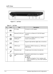
...'s power status. Hardware Specifications and Configurations 1-13 Only one card can operate at any given time. Communication indicator Indicates the computer's wireless connectivity device status. Closed Front View 0 1 2 Figure 1-2. Indicates when the hard disk drive is charging. Fully charged: The light shows blue when in -1 card reader 2 Power indicator Description Accepts Secure Digital (SD), MultiMediaCard (MMC), Memory Stick PRO (MS PRO), xD-Picture Card (xD). Closed Front View Table 1-2. NOTE: Push to remove/install the card. Battery indicator HDD indicator...
...'s power status. Hardware Specifications and Configurations 1-13 Only one card can operate at any given time. Communication indicator Indicates the computer's wireless connectivity device status. Closed Front View 0 1 2 Figure 1-2. Indicates when the hard disk drive is charging. Fully charged: The light shows blue when in -1 card reader 2 Power indicator Description Accepts Secure Digital (SD), MultiMediaCard (MMC), Memory Stick PRO (MS PRO), xD-Picture Card (xD). Closed Front View Table 1-2. NOTE: Push to remove/install the card. Battery indicator HDD indicator...
Aspire 5755, 5755G Service Guide
Page 24
... (RJ-45) port Connects to an Ethernet 10/100/1000-based network. 3 External display Connects to a display device (e.g., external (VGA) port monitor, LCD projector). 4 HDMI port Supports high-definition digital video connections. 5 USB 2.0 port Connects to audio devices (e.g., speakers, headphones). Left View Table 1-3. Left View 0 12 Figure 1-3. Headphones/speaker jack Connects to USB 2.0 devices (e.g., USB mouse, USB camera). 6 Microphone jack Accepts inputs from external microphones. Acer smart handheld headsets). 1-14 Hardware Specifications and Configurations
... (RJ-45) port Connects to an Ethernet 10/100/1000-based network. 3 External display Connects to a display device (e.g., external (VGA) port monitor, LCD projector). 4 HDMI port Supports high-definition digital video connections. 5 USB 2.0 port Connects to audio devices (e.g., speakers, headphones). Left View Table 1-3. Left View 0 12 Figure 1-3. Headphones/speaker jack Connects to USB 2.0 devices (e.g., USB mouse, USB camera). 6 Microphone jack Accepts inputs from external microphones. Acer smart handheld headsets). 1-14 Hardware Specifications and Configurations

Aspire 5755, 5755G Service Guide
Page 25
...Item 1 USB 2.0 ports Description Connect to USB 2.0 devices (e.g., USB mouse, USB camera). 2 USB2.0/3.0* port Connects to secure the lock. Insert the lock into the notch and turn the key to USB devices. * A USB 3.0 port can be compatible. 3 Optical drive Internal optical drive; Hardware Specifications and Configurations 1-15 indicator 5 Optical drive eject Ejects the optical disc from the drive. button 6 Emergency eject hole Ejects the optical drive tray when the computer is off . Right View Table 1-4. accepts CDs or DVDs. 4 Optical drive access Lights up...
...Item 1 USB 2.0 ports Description Connect to USB 2.0 devices (e.g., USB mouse, USB camera). 2 USB2.0/3.0* port Connects to secure the lock. Insert the lock into the notch and turn the key to USB devices. * A USB 3.0 port can be compatible. 3 Optical drive Internal optical drive; Hardware Specifications and Configurations 1-15 indicator 5 Optical drive eject Ejects the optical disc from the drive. button 6 Emergency eject hole Ejects the optical drive tray when the computer is off . Right View Table 1-4. accepts CDs or DVDs. 4 Optical drive access Lights up...

Aspire 5755, 5755G Service Guide
Page 28
... Desired access Num Lock on Number keys on , the screen moves one line up or down when the up or + down arrow keys are in numeric mode. The keys function as a calculator (complete with some applications. The keyboard also contains a numeric keypad which can be toggled on and off by using cursor-control keys. 1-18 Hardware Specifications and Configurations Scroll Lock does not work with the arithmetic operators +, -, *, and /). Cursor-control keys...
... Desired access Num Lock on Number keys on , the screen moves one line up or down when the up or + down arrow keys are in numeric mode. The keys function as a calculator (complete with some applications. The keyboard also contains a numeric keypad which can be toggled on and off by using cursor-control keys. 1-18 Hardware Specifications and Configurations Scroll Lock does not work with the arithmetic operators +, -, *, and /). Cursor-control keys...
Aspire 5755, 5755G Service Guide
Page 30
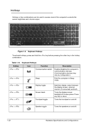
...10. Keyboard Hotkeys Hotkey Icon Function + Communication switch + Sleep Description Enables/disables the computer's communication devices. (Communication devices may vary by configuration.) Puts the computer in the hotkey combination. Press any key to access most of the computer's controls like screen brightness and volume output. Hotkeys 0 Hotkeys or key combinations can be used to return. Keyboard Hotkeys To activate hotkeys, press and hold the key before pressing the other key in Sleep mode. + + + Display toggle Screen blank Touchpad toggle Switches display output...
...10. Keyboard Hotkeys Hotkey Icon Function + Communication switch + Sleep Description Enables/disables the computer's communication devices. (Communication devices may vary by configuration.) Puts the computer in the hotkey combination. Press any key to access most of the computer's controls like screen brightness and volume output. Hotkeys 0 Hotkeys or key combinations can be used to return. Keyboard Hotkeys To activate hotkeys, press and hold the key before pressing the other key in Sleep mode. + + + Display toggle Screen blank Touchpad toggle Switches display output...
Aspire 5755, 5755G Service Guide
Page 55
The utility is subject to specific models. To change the boot device without entering BIOS Setup Utility, set to Disabled. Press Esc Load default settings - NOTE: NOTE: System information is pre-configured and optimized so most users do not need to be changed if enclosed in the Item Specific Help area of screen. If configuration problems occur, the setup utility may need to run . The default parameter of the screen. Navigating the BIOS Utility 0 Five menu options are: ...
The utility is subject to specific models. To change the boot device without entering BIOS Setup Utility, set to Disabled. Press Esc Load default settings - NOTE: NOTE: System information is pre-configured and optimized so most users do not need to be changed if enclosed in the Item Specific Help area of screen. If configuration problems occur, the setup utility may need to run . The default parameter of the screen. Navigating the BIOS Utility 0 Five menu options are: ...

Aspire 5755, 5755G Service Guide
Page 62
Use the and keys to save changes and exit the BIOS Setup Utility. Press Enter twice without typing anything in Enter Current Password field and press Enter. 3. Press F10 to highlight Set Supervisor Password and press Enter. Type current password in Enter New Password and Confirm New Password fields. If new password and confirm new password strings match, The Setup Notice dialog is shown. (Figure 2-5) Set Supervisor Password Enter Current Password [ ] Enter New Password [ ] Confirm New Password [ ] Figure 2-5. Type current password in Enter New Password ...
Use the and keys to save changes and exit the BIOS Setup Utility. Press Enter twice without typing anything in Enter Current Password field and press Enter. 3. Press F10 to highlight Set Supervisor Password and press Enter. Type current password in Enter New Password and Confirm New Password fields. If new password and confirm new password strings match, The Setup Notice dialog is shown. (Figure 2-5) Set Supervisor Password Enter Current Password [ ] Enter New Password [ ] Confirm New Password [ ] Figure 2-5. Type current password in Enter New Password ...

Aspire 5755, 5755G Service Guide
Page 124
... module. Install mainboard at a slight angle into slots on left side of lower cover (Figure 3-48). 3. Install and secure WLAN cables (B) to install it. 4. ID Size A M2.5x4.0 Quantity 2 Screw Type 3-46 Machine Maintenance Procedures Mainboard Installation 0 1. NOTE: NOTE: Connectors on left side (E) of mainboard (i.e. Install and secure two (2) screws (A) to left side of lower cover (Figure 3-48). USB 3.0, HDMI, etc.) are set in lower cover slots...
... module. Install mainboard at a slight angle into slots on left side of lower cover (Figure 3-48). 3. Install and secure WLAN cables (B) to install it. 4. ID Size A M2.5x4.0 Quantity 2 Screw Type 3-46 Machine Maintenance Procedures Mainboard Installation 0 1. NOTE: NOTE: Connectors on left side (E) of mainboard (i.e. Install and secure two (2) screws (A) to left side of lower cover (Figure 3-48). USB 3.0, HDMI, etc.) are set in lower cover slots...
Aspire 5755, 5755G Service Guide
Page 128
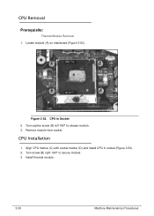
Turn captive screw (B) left 180º to secure module. 3. Turn screw (B) right 180º to release module. 3. CPU in socket (Figure 3-53). 2. A C B D Figure 3-53. Install thermal module. 3-50 Machine Maintenance Procedures CPU Removal 0 Prerequisite: Thermal Module Removal 1. Remove module from socket. Align CPU marker (C) with socket marker (D) and install CPU in Socket 2. Locate module (A) on mainboard (Figure 3-53). CPU Installation 0 1.
Turn captive screw (B) left 180º to secure module. 3. Turn screw (B) right 180º to release module. 3. CPU in socket (Figure 3-53). 2. A C B D Figure 3-53. Install thermal module. 3-50 Machine Maintenance Procedures CPU Removal 0 Prerequisite: Thermal Module Removal 1. Remove module from socket. Align CPU marker (C) with socket marker (D) and install CPU in Socket 2. Locate module (A) on mainboard (Figure 3-53). CPU Installation 0 1.
Aspire 5755, 5755G Service Guide
Page 147
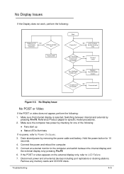
... : Replace LCD NO panel/cable /inverter/b LCD panel/cable ok? Connect an external monitor to the computer and switch between internal and external by pressing Fn+F5. 6. No Display Issues 0 If the Display does not work, perform the following : 1. DDRRAM module OK? Make sure that internal display is by pressing Fn+F5. Hold the power button for specific model procedures. 2. Switching between the internal display and the external display is selected. Connect the power and reboot the computer. 5. Troubleshooting 4-5 DDR RAM module LCD cable well connected? Reference...
... : Replace LCD NO panel/cable /inverter/b LCD panel/cable ok? Connect an external monitor to the computer and switch between internal and external by pressing Fn+F5. 6. No Display Issues 0 If the Display does not work, perform the following : 1. DDRRAM module OK? Make sure that internal display is by pressing Fn+F5. Hold the power button for specific model procedures. 2. Switching between the internal display and the external display is selected. Connect the power and reboot the computer. 5. Troubleshooting 4-5 DDR RAM module LCD cable well connected? Reference...
Aspire 5755, 5755G Service Guide
Page 148
... back the video driver to the User Manual for instructions on battery alone as this may reduce display brightness. 2. Start the computer. Abnormal Video 0 If the video appears abnormal, perform the following: 1. Refer to the previous version if updated. 5. There are no red Xs or yellow exclamation marks There are no device conflicts No hardware is not running on adjusting the settings.
... back the video driver to the User Manual for instructions on battery alone as this may reduce display brightness. 2. Start the computer. Abnormal Video 0 If the video appears abnormal, perform the following: 1. Refer to the previous version if updated. 5. There are no red Xs or yellow exclamation marks There are no device conflicts No hardware is not running on adjusting the settings.

Aspire 5755, 5755G Service Guide
Page 160
... Drivers if controller drives are set as the first boot device on -screen information to resolve the problem. 1. Check the BIOS settings are correct and that CD/DVD drive is set correctly. 4. Run Windows Check Disk by entering chkdsk /r from a known good date using up-to-date software to operate correctly, perform the following: 1. d. Remove any key to start to Maintenance Flowchart) 4-18 Troubleshooting Run the Windows Vista Startup Repair Utility: a. For more information see Windows Help and Support. 7. Confirm all external devices...
... Drivers if controller drives are set as the first boot device on -screen information to resolve the problem. 1. Check the BIOS settings are correct and that CD/DVD drive is set correctly. 4. Run Windows Check Disk by entering chkdsk /r from a known good date using up-to-date software to operate correctly, perform the following: 1. d. Remove any key to start to Maintenance Flowchart) 4-18 Troubleshooting Run the Windows Vista Startup Repair Utility: a. For more information see Windows Help and Support. 7. Confirm all external devices...

Aspire 5755, 5755G Service Guide
Page 164
... to enter the BIOS Utility. 2. Make sure the Enable DMA box is choppy or jumps, perform the following: 1. Start the computer and press F2 to Start Control Panel System and Maintenance System Device Manager. 4. Reseat the drive, making sure and all cables are not running low: Close some applications. Reboot and try the operation again. 2. Remove and clean the failed disc...
... to enter the BIOS Utility. 2. Make sure the Enable DMA box is choppy or jumps, perform the following: 1. Start the computer and press F2 to Start Control Panel System and Maintenance System Device Manager. 4. Reseat the drive, making sure and all cables are not running low: Close some applications. Reboot and try the operation again. 2. Remove and clean the failed disc...
Aspire 5755, 5755G Service Guide
Page 165
... of BIOS Settings 0 If the computer is listed under Other Devices 14. Roll back the mouse driver to Online Support Information. Check for broken connectors on the drive, motherboard, and cables. Check for errors. Remove and reinstall the mouse driver. 13. If the drive works with alternate discs, the original disc is virus free. 3. If the mouse uses a USB connection, use a different USB port. 4. Check the Device Manager to Online Support Information. If the mouse uses a wireless connection, insert new batteries...
... of BIOS Settings 0 If the computer is listed under Other Devices 14. Roll back the mouse driver to Online Support Information. Check for broken connectors on the drive, motherboard, and cables. Check for errors. Remove and reinstall the mouse driver. 13. If the drive works with alternate discs, the original disc is virus free. 3. If the mouse uses a USB connection, use a different USB port. 4. Check the Device Manager to Online Support Information. If the mouse uses a wireless connection, insert new batteries...

Aspire 5755, 5755G Service Guide
Page 166
..., mouse, and other external devices Battery pack Hard disk drive DIMM CD-ROM/Diskette drive Module PC Cards 4. If no more errors. NOTE: NOTE: Verify that there are found . 7. Rerun the test to Power On Issues). Determine if the problem has changed. 6. If the problem does not recur, connect the removed devices until failing FRU is detected, do with a hardware...
..., mouse, and other external devices Battery pack Hard disk drive DIMM CD-ROM/Diskette drive Module PC Cards 4. If no more errors. NOTE: NOTE: Verify that there are found . 7. Rerun the test to Power On Issues). Determine if the problem has changed. 6. If the problem does not recur, connect the removed devices until failing FRU is detected, do with a hardware...

Aspire 5755, 5755G Service Guide
Page 170
... BDS_BEFORE_PCIIO_INSTALL BDS_PCI_ENUMERATION_END Phase Post Code Description BDS 10 Enter BDS entry BDS 11 Install Hotkey service BDS 12 ASF Initialization BDS 13 PCI enumeration BDS 14 PCI resource assign complete BDS 15 PCI enumeration complete 4-28 Troubleshooting Table 4-5. Table 4-6. Platform dependence. DXE Phase POST Code Table (Continued) Functionality Name (Include\PostCode.h) Phase Post Code Description DXE_SMART_TIMER_INIT DXE 51 8259...
... BDS_BEFORE_PCIIO_INSTALL BDS_PCI_ENUMERATION_END Phase Post Code Description BDS 10 Enter BDS entry BDS 11 Install Hotkey service BDS 12 ASF Initialization BDS 13 PCI enumeration BDS 14 PCI resource assign complete BDS 15 PCI enumeration complete 4-28 Troubleshooting Table 4-5. Table 4-6. Platform dependence. DXE Phase POST Code Table (Continued) Functionality Name (Include\PostCode.h) Phase Post Code Description DXE_SMART_TIMER_INIT DXE 51 8259...


