
Quick Start Guide
Page 9
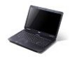
..., LCD projector). Note: Push to remove/install the card. Left view # Icon 1 2 3 4 5 12 3 Item DC-in -1 card reader Accepts Secure Digital (SD), MultiMediaCard (MMC), Memory Stick (MS), Memory Stick PRO (MS PRO), xDPicture Card (xD). 7 Closed front view English # Icon 1 Item Description Multi-in jack 4 5 Description Connects to an AC adapter. Microphone...
..., LCD projector). Note: Push to remove/install the card. Left view # Icon 1 2 3 4 5 12 3 Item DC-in -1 card reader Accepts Secure Digital (SD), MultiMediaCard (MMC), Memory Stick (MS), Memory Stick PRO (MS PRO), xDPicture Card (xD). 7 Closed front view English # Icon 1 Item Description Multi-in jack 4 5 Description Connects to an AC adapter. Microphone...
Quick Start Guide
Page 11
...; Operating: 20% to 80% • Non-operating: 20% to stay cool, even after prolonged use. Battery lock Locks the battery in position. Memory compartment Houses the computer's main memory. Ventilation slots and cooling fan Enable the computer to 80% Note: Do not cover or obstruct the opening of the fan. English 9 Base...
...; Operating: 20% to 80% • Non-operating: 20% to stay cool, even after prolonged use. Battery lock Locks the battery in position. Memory compartment Houses the computer's main memory. Ventilation slots and cooling fan Enable the computer to 80% Note: Do not cover or obstruct the opening of the fan. English 9 Base...
Service Guide
Page 5
add-on your regional Acer office to extend the functionality of customer machines. In... the following general information. 1. V These LOCALIZED FEATURES will not be covered in this generic service guide. For ACER-AUTHORIZED SERVICE PROVIDERS, your regional office MAY have a DIFFERENT part number code to the BASIC CONFIGURATION decided for repair...Service Guide. To better fit local market requirements and enhance product competitiveness, your Acer office may have decided to order FRU parts for Acer's "global" product offering. Please note WHEN ORDERING FRU PARTS, that you ...
add-on your regional Acer office to extend the functionality of customer machines. In... the following general information. 1. V These LOCALIZED FEATURES will not be covered in this generic service guide. For ACER-AUTHORIZED SERVICE PROVIDERS, your regional office MAY have a DIFFERENT part number code to the BASIC CONFIGURATION decided for repair...Service Guide. To better fit local market requirements and enhance product competitiveness, your Acer office may have decided to order FRU parts for Acer's "global" product offering. Please note WHEN ORDERING FRU PARTS, that you ...
Service Guide
Page 11
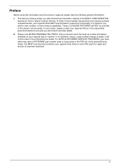
Operating System • Genuine Windows® 7 Home Premium 64-bit • Genuine Windows® 7 Home Basic 64-bit Platform Aspire 5334 • Intel® Celeron® processor T3100/T3000 (1 MB L2 cache, 1.80/1.90 GHz, 800 MHz FSB, 35 W), T1600/T1700 (1 MB L2 cache, 1.66/1.83 ... summary of the computer's many features: NOTE: Items denoted with up to 1759 MB of Intel® Dynamic Video Memory Technology 5.0 (64 MB of dedicated system memory, up to 1695 MB of DDR3 system memory, upgradable to 2560 x 1600: 60 Hz • MPEG-2/DVD decoding • WMV9 (VC-1) and H.264 (AVC) decoding ...
Operating System • Genuine Windows® 7 Home Premium 64-bit • Genuine Windows® 7 Home Basic 64-bit Platform Aspire 5334 • Intel® Celeron® processor T3100/T3000 (1 MB L2 cache, 1.80/1.90 GHz, 800 MHz FSB, 35 W), T1600/T1700 (1 MB L2 cache, 1.66/1.83 ... summary of the computer's many features: NOTE: Items denoted with up to 1759 MB of Intel® Dynamic Video Memory Technology 5.0 (64 MB of dedicated system memory, up to 1695 MB of DDR3 system memory, upgradable to 2560 x 1600: 60 Hz • MPEG-2/DVD decoding • WMV9 (VC-1) and H.264 (AVC) decoding ...
Service Guide
Page 12
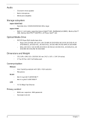
...in microphone MS-Sound compatible Storage subsystem Aspire 5334/5734Z • Hard disk drive: 160/250/320/500/640 GB or larger Aspire 5734Z • Multi-in-1 card reader, supporting Secure Digital™ (SD), MultiMediaCard (MMC), Memory Stick™ (MS), Memory Stick PRO™ (MS PRO), ... (D) x 26.8/39.6 (H) mm (14.51 x 9.61 x 1.04/1.54 inches) • 2.7 kg (6.0 lbs.) with 6-cell battery pack Communication Webcam • Acer Crystal Eye webcam with 1280 x 1024 resolution • Microphone WLAN • 802.11 b/g/n Wi-Fi CERTIFIED™ • 802.11 b/g Wi-Fi CERTIFIED™ LAN...
...in microphone MS-Sound compatible Storage subsystem Aspire 5334/5734Z • Hard disk drive: 160/250/320/500/640 GB or larger Aspire 5734Z • Multi-in-1 card reader, supporting Secure Digital™ (SD), MultiMediaCard (MMC), Memory Stick™ (MS), Memory Stick PRO™ (MS PRO), ... (D) x 26.8/39.6 (H) mm (14.51 x 9.61 x 1.04/1.54 inches) • 2.7 kg (6.0 lbs.) with 6-cell battery pack Communication Webcam • Acer Crystal Eye webcam with 1280 x 1024 resolution • Microphone WLAN • 802.11 b/g/n Wi-Fi CERTIFIED™ • 802.11 b/g Wi-Fi CERTIFIED™ LAN...
Service Guide
Page 17
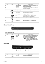
Turns the internal touchpad on and off . Closed Front View Aspire 5734Z model only No. 1 Icon Item 5-in jack Description Connects to remove/install the card. Only one card can operate at any given time. Communication ... microphone for your hands when you use the computer. No. 1 Icon Item DC-in -1 card reader Left View Description Accepts Secure Digital (SD), MultiMediaCard (MMC), Memory Stick (MS), Memory Stick PRO (MS PRO), xDPicture Card (xD).
Turns the internal touchpad on and off . Closed Front View Aspire 5734Z model only No. 1 Icon Item 5-in jack Description Connects to remove/install the card. Only one card can operate at any given time. Communication ... microphone for your hands when you use the computer. No. 1 Icon Item DC-in -1 card reader Left View Description Accepts Secure Digital (SD), MultiMediaCard (MMC), Memory Stick (MS), Memory Stick PRO (MS PRO), xDPicture Card (xD).
Service Guide
Page 20
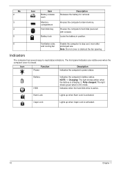
... the computer to -read status indicators. Num Lock Lights up when Caps Lock is activated. 10 Chapter 1 Houses the computer's main memory. Indicators The computer has several easy-to stay cool, even after and cooling fan prolonged use. Charging: The light shows amber when ...the battery is activated. No. 2 3 4 5 Icon Item Battery release latch Memory compartment Hard disk bay Battery lock Description Releases the battery for removal. Houses the computer's hard disk (secured with screws). Note: Do not...
... the computer to -read status indicators. Num Lock Lights up when Caps Lock is activated. 10 Chapter 1 Houses the computer's main memory. Indicators The computer has several easy-to stay cool, even after and cooling fan prolonged use. Charging: The light shows amber when ...the battery is activated. No. 2 3 4 5 Icon Item Battery release latch Memory compartment Hard disk bay Battery lock Description Releases the battery for removal. Houses the computer's hard disk (secured with screws). Note: Do not...
Service Guide
Page 26
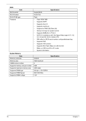
... Version BIOS ROM type Features System Memory Item Memory controller Memory size DIMM socket number Supports memory size per socket Supports maximum memory size Supports DIMM type Supports DIMM Speed Supports DIMM voltage Specification Insyde BIOS V0.06-T02 Flash • Flash ROM 1MB • Supports ISIPP • Supports Acer UI • Supports multi-boot •...
... Version BIOS ROM type Features System Memory Item Memory controller Memory size DIMM socket number Supports memory size per socket Supports maximum memory size Supports DIMM type Supports DIMM Speed Supports DIMM voltage Specification Insyde BIOS V0.06-T02 Flash • Flash ROM 1MB • Supports ISIPP • Supports Acer UI • Supports multi-boot •...
Service Guide
Page 27
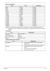
... 2048MB 2048MB 2048MB 2048MB 512MB 1024MB 2048MB 512MB 1024MB 2048MB 0MB 512MB 1024MB 2048MB 0MB 512MB 1024MB 2048MB Slot 2 Total Memory 512MB 1024MB 2048MB 1024MB 1536MB 2560MB 1024MB 1536MB 2048MB 3072MB 2048MB 2560MB 3072MB 4096MB NOTE: Above table lists some system... memory configurations. You may combine DIMMs with dual-band, built-in antenna • Acer InviLink™ 802.11b/g/Draft-N* • Acer InviLink™ 802.11b/g* Chapter 1 17 LAN Interface Item LAN Chipset Atheros AR8132L...
... 2048MB 2048MB 2048MB 2048MB 512MB 1024MB 2048MB 512MB 1024MB 2048MB 0MB 512MB 1024MB 2048MB 0MB 512MB 1024MB 2048MB Slot 2 Total Memory 512MB 1024MB 2048MB 1024MB 1536MB 2560MB 1024MB 1536MB 2048MB 3072MB 2048MB 2560MB 3072MB 4096MB NOTE: Above table lists some system... memory configurations. You may combine DIMMs with dual-band, built-in antenna • Acer InviLink™ 802.11b/g/Draft-N* • Acer InviLink™ 802.11b/g* Chapter 1 17 LAN Interface Item LAN Chipset Atheros AR8132L...
Service Guide
Page 29
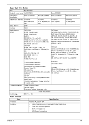
... disc CD-ROM Mode-2 data disc DVD Write: DVD Data & Video CD-ROM XA, CD-I, Photo-CD Multi- Sustained: 11.08 Mbytes/s (8x) max. Buffer Memory 2 MB Interface SATA Applicable disc formats DVD-ROM: 4.7GB (Single Layer) 8.5GB (Dual Layer) DVD-R: 3.95GB (Ver. 1.0: read only) 4.7GB (Ver. 2.0 for Authoring: read only...
... disc CD-ROM Mode-2 data disc DVD Write: DVD Data & Video CD-ROM XA, CD-I, Photo-CD Multi- Sustained: 11.08 Mbytes/s (8x) max. Buffer Memory 2 MB Interface SATA Applicable disc formats DVD-ROM: 4.7GB (Single Layer) 8.5GB (Dual Layer) DVD-R: 3.95GB (Ver. 1.0: read only) 4.7GB (Ver. 2.0 for Authoring: read only...
Service Guide
Page 35
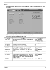
...and date as well as enable and disable boot option and recovery. Information Main InsydeH20 Setup Utility Security Boot Exit System Time: System Date: Total Memory: Video Memory: Quiet Boot Network Boot F12 Boot Menu D2D Recovery SATA Mode [22:37:05] [01/16/2010] 2047 MB [64 MB] [Enabled]... Values F9 Setup Default Select Menu Enter Select SubMenu F10 Save and Exit NOTE: The screen above is from LAN (remote server). Displays the total memory available. Enables, disables Boot Menu during POST. Format/Option Format: HH:MM:SS (hour:minute:second) Format MM/DD/YYYY (month/day/year)...
...and date as well as enable and disable boot option and recovery. Information Main InsydeH20 Setup Utility Security Boot Exit System Time: System Date: Total Memory: Video Memory: Quiet Boot Network Boot F12 Boot Menu D2D Recovery SATA Mode [22:37:05] [01/16/2010] 2047 MB [64 MB] [Enabled]... Values F9 Setup Default Select Menu Enter Select SubMenu F10 Save and Exit NOTE: The screen above is from LAN (remote server). Displays the total memory available. Enables, disables Boot Menu during POST. Format/Option Format: HH:MM:SS (hour:minute:second) Format MM/DD/YYYY (month/day/year)...
Service Guide
Page 41
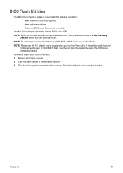
... run the Flash utility. Copy the flash utilities to update the system BIOS flash ROM. BIOS Flash Utilities The BIOS flash memory update is not completely loaded. NOTE: Do not install memory-related drivers (XMS, EMS, DPMI) when you use the AC adaptor power supply when you use the Flash utility. Use...
... run the Flash utility. Copy the flash utilities to update the system BIOS flash ROM. BIOS Flash Utilities The BIOS flash memory update is not completely loaded. NOTE: Do not install memory-related drivers (XMS, EMS, DPMI) when you use the AC adaptor power supply when you use the Flash utility. Use...
Service Guide
Page 48
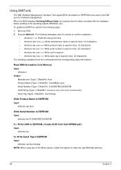
... to EEPROM ( Create UUID from Memory Input: dmitools /r Output: Manufacturer (Type1, Offset04h): Acer Product Name (Type1, Offset05h): TravelMate xxxxx Serial Number (Type1, Offset07h): 01234567890123456789 UUID String (Type1, Offset08h): xxxxxxxx-xxxx-xxxx-xxxx-xxxxxxxxxxxx Asset Tag (Type3, Offset04h): Acet Asstag Write Product Name to EEPROM Input: dmitools /wp Acer Write Serial Number to EEPROM...
... to EEPROM ( Create UUID from Memory Input: dmitools /r Output: Manufacturer (Type1, Offset04h): Acer Product Name (Type1, Offset05h): TravelMate xxxxx Serial Number (Type1, Offset07h): 01234567890123456789 UUID String (Type1, Offset08h): xxxxxxxx-xxxx-xxxx-xxxx-xxxxxxxxxxxx Asset Tag (Type3, Offset04h): Acet Asstag Write Product Name to EEPROM Input: dmitools /wp Acer Write Serial Number to EEPROM...
Service Guide
Page 58
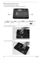
Carefully open the Memory Cover. 48 Chapter 3 Memory Cover HDD Cover Step Lower Covers Size M2.5*8 3. See "Removing the Battery Pack" on page 46. 2. Remove the three (3) screws securing the Memory and HDD Covers. Remove the HDD cover as shown. Removing the Lower Covers 1. Quantity 3 Screw Type 4.
Carefully open the Memory Cover. 48 Chapter 3 Memory Cover HDD Cover Step Lower Covers Size M2.5*8 3. See "Removing the Battery Pack" on page 46. 2. Remove the three (3) screws securing the Memory and HDD Covers. Remove the HDD cover as shown. Removing the Lower Covers 1. Quantity 3 Screw Type 4.
Service Guide
Page 130
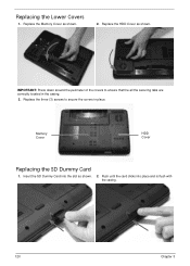
Memory Cover HDD Cover Replacing the SD Dummy Card 1. Replace the three (3) screws to ensure that the all the securing tabs are correctly located in place. Insert the SD Dummy Card into place and is flush with the casing. 120 Chapter 3 Replace the HDD Cover as shown. 2. Replace the Memory Cover as shown. 2. Push until the card clicks into the slot as shown. IMPORTANT: Press down around the perimeter of the covers to secure the covers in the casing. 3. Replacing the Lower Covers 1.
Memory Cover HDD Cover Replacing the SD Dummy Card 1. Replace the three (3) screws to ensure that the all the securing tabs are correctly located in place. Insert the SD Dummy Card into place and is flush with the casing. 120 Chapter 3 Replace the HDD Cover as shown. 2. Replace the Memory Cover as shown. 2. Push until the card clicks into the slot as shown. IMPORTANT: Press down around the perimeter of the covers to secure the covers in the casing. 3. Replacing the Lower Covers 1.
Service Guide
Page 135
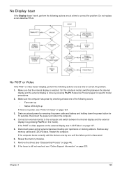
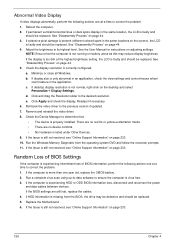
... No POST or Video If the POST or video doesn't display, perform the following actions one at a time to correct the problem. Drain any memory cards and CD/DVD discs. If the POST or video appears on the external display, see "Online Support Information" on page 124. 3. Reference ... Make sure the computer has power by removing the power cable and battery and holding down the power button for specific model procedures. 2. Reseat the memory modules. 7. Remove the drives (see "Power On Issue" on page 233. No Display Issue If the Display doesn't work, perform the following actions...
... No POST or Video If the POST or video doesn't display, perform the following actions one at a time to correct the problem. Drain any memory cards and CD/DVD discs. If the POST or video appears on the external display, see "Online Support Information" on page 124. 3. Reference ... Make sure the computer has power by removing the power cable and battery and holding down the power button for specific model procedures. 2. Reseat the memory modules. 7. Remove the drives (see "Power On Issue" on page 233. No Display Issue If the Display doesn't work, perform the following actions...
Service Guide
Page 136
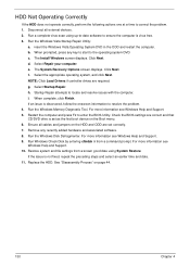
... battery alone as this may be defective and should be replaced. If the Issue is not normal, right-click on adjusting settings. Run the Windows Memory Diagnostic from the BIOS, the drive may reduce display brightness. If the computer is experiencing HDD or ODD BIOS information loss, disconnect and reconnect the...
... battery alone as this may be defective and should be replaced. If the Issue is not normal, right-click on adjusting settings. Run the Windows Memory Diagnostic from the BIOS, the drive may reduce display brightness. If the computer is experiencing HDD or ODD BIOS information loss, disconnect and reconnect the...
Service Guide
Page 140
... any recently added hardware and associated software. 8. The Install Windows screen displays. Click Next. Select the appropriate operating system, and click Next. Run the Windows Memory Diagnostic Tool. Restart the computer and press F2 to locate and resolve issues with the computer. Click Next. Select Repair your computer. For more information...
... any recently added hardware and associated software. 8. The Install Windows screen displays. Click Next. Select the appropriate operating system, and click Next. Run the Windows Memory Diagnostic Tool. Restart the computer and press F2 to locate and resolve issues with the computer. Click Next. Select Repair your computer. For more information...

Service Guide
Page 147
...and not asymmetric Verify all DIMMs are x8 or x16 width Find a common CAS latency between the DIMMS and the MCH Determine the memory frequency and CAS latency to program Determine the smallest common TRAS for all DIMMs Determine the smallest common TRP for all DIMMs Determine the...burst length of 8 is supported by all DIMMs Determine the smallest tWR supported by all DIMMs Determine the smallest refresh period for the memory channels Program clock crossing registers Disable Fast Dispatch Program the DRAM Row Attributes and DRAM Row Boundary registers Program the DRAM Bank Architecture register...
...and not asymmetric Verify all DIMMs are x8 or x16 width Find a common CAS latency between the DIMMS and the MCH Determine the memory frequency and CAS latency to program Determine the smallest common TRAS for all DIMMs Determine the smallest common TRP for all DIMMs Determine the...burst length of 8 is supported by all DIMMs Determine the smallest tWR supported by all DIMMs Determine the smallest refresh period for the memory channels Program clock crossing registers Disable Fast Dispatch Program the DRAM Row Attributes and DRAM Row Boundary registers Program the DRAM Bank Architecture register...

Service Guide
Page 148
Code 0x28 0x29 0x30 0x31 0x32 0x33 0x34 0x35 0xAF Description Enable all clocks on populated rows Perform JEDEC memory initialization for all memory rows Perform steps required after memory init Program DRAM throttling and throttling event registers Setup DRAM control register for normal operation and enable Enable RCOMP Clear DRAM initialization bit in the SB Initialization Sequence Completed, program graphic clocks Disable access to the XMM registers 138 Chapter 4
Code 0x28 0x29 0x30 0x31 0x32 0x33 0x34 0x35 0xAF Description Enable all clocks on populated rows Perform JEDEC memory initialization for all memory rows Perform steps required after memory init Program DRAM throttling and throttling event registers Setup DRAM control register for normal operation and enable Enable RCOMP Clear DRAM initialization bit in the SB Initialization Sequence Completed, program graphic clocks Disable access to the XMM registers 138 Chapter 4


