Quick Start Guide
Page 6
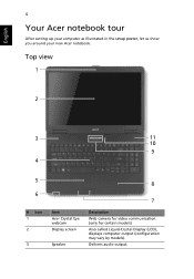
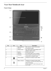
English 4 Your Acer notebook tour After setting up your computer as illustrated in the setup poster, let us show you around your new Acer notebook. Delivers audio output. Top view 1 2 3 11 10 9 4 5 6 # Icon 1 2 3 Item Acer Crystal Eye webcam Display screen Speaker 8 7 Description Web camera for video communication. (only for certain models) Also called Liquid-Crystal Display (LCD), displays computer output (configuration may vary by models).
English 4 Your Acer notebook tour After setting up your computer as illustrated in the setup poster, let us show you around your new Acer notebook. Delivers audio output. Top view 1 2 3 11 10 9 4 5 6 # Icon 1 2 3 Item Acer Crystal Eye webcam Display screen Speaker 8 7 Description Web camera for video communication. (only for certain models) Also called Liquid-Crystal Display (LCD), displays computer output (configuration may vary by models).

Quick Start Guide
Page 9
.../install the card. External display (VGA) Connects to an Ethernet 10/100-based network. Ethernet (RJ-45) port Connects to a display device port (e.g., external monitor, LCD projector).
.../install the card. External display (VGA) Connects to an Ethernet 10/100-based network. Ethernet (RJ-45) port Connects to a display device port (e.g., external monitor, LCD projector).
Quick Start Guide
Page 268
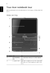
4 한 Your Acer notebook tour 국 어 Acer 입니다 . 1 2 3 11 10 9 4 5 8 6 7 설명 1 Acer Crystal Eye 웹캠 해당 ). 2 LCD 니다 ).
4 한 Your Acer notebook tour 국 어 Acer 입니다 . 1 2 3 11 10 9 4 5 8 6 7 설명 1 Acer Crystal Eye 웹캠 해당 ). 2 LCD 니다 ).
Service Guide
Page 7
Table of Contents System Specifications 1 Features 1 Optical Media Drive 2 System Block Diagram 5 Your Acer Notebook tour 6 Front View 6 Closed Front View 7 Left View 7 Right View 9 Bottom View 9 Indicators 10 TouchPad Basics 11 Using the Keyboard 12 Lock Keys and ... Disk Drive Module 55 Removing the Switch Cover 57 Removing the Keyboard 58 Main Unit Disassembly Process 59 Main Unit Disassembly Flowchart 59 Removing the LCD Module 60 Removing the Upper Cover 65 Removing the Power Board 69 Removing the Left Speaker Module 70 Removing the TouchPad Bracket 72 VII
Table of Contents System Specifications 1 Features 1 Optical Media Drive 2 System Block Diagram 5 Your Acer Notebook tour 6 Front View 6 Closed Front View 7 Left View 7 Right View 9 Bottom View 9 Indicators 10 TouchPad Basics 11 Using the Keyboard 12 Lock Keys and ... Disk Drive Module 55 Removing the Switch Cover 57 Removing the Keyboard 58 Main Unit Disassembly Process 59 Main Unit Disassembly Flowchart 59 Removing the LCD Module 60 Removing the Upper Cover 65 Removing the Power Board 69 Removing the Left Speaker Module 70 Removing the TouchPad Bracket 72 VII
Service Guide
Page 8
...Replacing the TouchPad Bracket 101 Replacing the Left Speaker Module 103 Replacing the Power Board 103 Replacing the Upper Cover 105 Replacing the LCD Module 109 Replacing the Keyboard 114 Replacing the Switch Cover 115 Replacing the Hard Disk Drive Module 115 Replacing the WLAN Module ...Replacing the Battery 121 Troubleshooting 123 Common Problems 123 Power On Issue 124 No Display Issue 125 Random Loss of BIOS Settings 126 LCD Failure 127 Built-In Keyboard Failure 127 TouchPad Failure 128 Internal Speaker Failure 128 HDD Not Operating Correctly 130 ODD Failure 131 ...
...Replacing the TouchPad Bracket 101 Replacing the Left Speaker Module 103 Replacing the Power Board 103 Replacing the Upper Cover 105 Replacing the LCD Module 109 Replacing the Keyboard 114 Replacing the Switch Cover 115 Replacing the Hard Disk Drive Module 115 Replacing the WLAN Module ...Replacing the Battery 121 Troubleshooting 123 Common Problems 123 Power On Issue 124 No Display Issue 125 Random Loss of BIOS Settings 126 LCD Failure 127 Built-In Keyboard Failure 127 TouchPad Failure 128 Internal Speaker Failure 128 HDD Not Operating Correctly 130 ODD Failure 131 ...
Service Guide
Page 9
... CMOS Jumper 149 BIOS Recovery by Crisis Disk 150 FRU (Field Replaceable Unit) List 151 JE50_MV Exploded Diagrams 152 Main Assembly 152 Rear Assembly 153 LCD Assembly 154 JE50_MV FRU List 155 Screw List 163 Model Definition and Configuration 164 Test Compatible Components 219 Microsoft® Windows® 7 Environment Test 220...
... CMOS Jumper 149 BIOS Recovery by Crisis Disk 150 FRU (Field Replaceable Unit) List 151 JE50_MV Exploded Diagrams 152 Main Assembly 152 Rear Assembly 153 LCD Assembly 154 JE50_MV FRU List 155 Screw List 163 Model Definition and Configuration 164 Test Compatible Components 219 Microsoft® Windows® 7 Environment Test 220...
Service Guide
Page 16
... when the battery is charging. 2. Also called Liquid-Crystal Display (LCD), displays computer output. Indicates the computer's power status. Fully charged: The light shows green when in AC mode. Delivers audio output. Your Acer Notebook tour Front View No. 1 2 3 4 5 6 6 Icon Item Acer Crystal Eye webcam Display screen Speaker Keyboard Touchpad Power indicator Description...
... when the battery is charging. 2. Also called Liquid-Crystal Display (LCD), displays computer output. Indicates the computer's power status. Fully charged: The light shows green when in AC mode. Delivers audio output. Your Acer Notebook tour Front View No. 1 2 3 4 5 6 6 Icon Item Acer Crystal Eye webcam Display screen Speaker Keyboard Touchpad Power indicator Description...

Service Guide
Page 18
Connects to an Ethernet 10/100-based network. USB mouse, USB camera). speakers, headphones). 8 Chapter 1 No. 2 3 4 5 Icon Item Ethernet (RJ-45) port External display (VGA) port USB 2.0 ports Microphone-in jack Headphones/ speaker/line-out jack Description Connects to audio line-out devices (e.g. Connect to a display device (e.g. Connects to USB 2.0 devices (e.g. external monitor, LCD projector). Accepts input from external microphones.
Connects to an Ethernet 10/100-based network. USB mouse, USB camera). speakers, headphones). 8 Chapter 1 No. 2 3 4 5 Icon Item Ethernet (RJ-45) port External display (VGA) port USB 2.0 ports Microphone-in jack Headphones/ speaker/line-out jack Description Connects to audio line-out devices (e.g. Connect to a display device (e.g. Connects to USB 2.0 devices (e.g. external monitor, LCD projector). Accepts input from external microphones.
Service Guide
Page 30
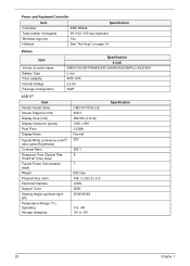
... Vendor & model name Battery Type Pack capacity Normal Voltage Package configuration Specification 6 Cell SANYO/SONY/PANASONIC/SAMSUNG/SIMPLO AS2009A Li-ion 4400 mAh 2.2 Ah 3S2P LCD 17" Item Vendor/model name Screen Diagonal (mm) Display Area (mm) Display resolution (pixels) Pixel Pitch Display Mode Typical White Luminance (cd/m2) (also called...
... Vendor & model name Battery Type Pack capacity Normal Voltage Package configuration Specification 6 Cell SANYO/SONY/PANASONIC/SAMSUNG/SIMPLO AS2009A Li-ion 4400 mAh 2.2 Ah 3S2P LCD 17" Item Vendor/model name Screen Diagonal (mm) Display Area (mm) Display resolution (pixels) Pixel Pitch Display Mode Typical White Luminance (cd/m2) (also called...
Service Guide
Page 31
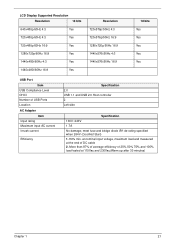
at nominal input voltage, maximum load and measured at 115Vac and 230Vac(Warm up after 30 minutes) Chapter 1 21 LCD Display Supported Resolution Resolution 18 bits 640x480p/60Hz 4:3 Yes 720x480p/60Hz 4:3 Yes 720x480p/60Hz 16:9 Yes 1280x720p/60Hz 16:9 Yes 1440x480i/60Hz 4:3 Yes 1440x480i/60Hz ...
at nominal input voltage, maximum load and measured at 115Vac and 230Vac(Warm up after 30 minutes) Chapter 1 21 LCD Display Supported Resolution Resolution 18 bits 640x480p/60Hz 4:3 Yes 720x480p/60Hz 4:3 Yes 720x480p/60Hz 16:9 Yes 1280x720p/60Hz 16:9 Yes 1440x480i/60Hz 4:3 Yes 1440x480i/60Hz ...
Service Guide
Page 54
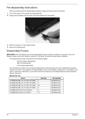
... you do the following: 1. Pre-disassembly Instructions Before proceeding with the disassembly procedure, make sure that order. Disassembly Process IMPORTANT: The LCD Module cannot be replaced. Main Screw List Screw Quantity Part Number SCREW M2.48D 4.0L K 5.5D 0.8T ZKNL 1 86.NAF02....+ 17 86.NAF02.006 44 Chapter 3 Remove the battery pack. The disassembly process is faulty, such as the camera, antenna or LCD panel, the whole module must first remove the keyboard, then disassemble the inside assembly frame in the succeeding disassembly sections illustrate the entire ...
... you do the following: 1. Pre-disassembly Instructions Before proceeding with the disassembly procedure, make sure that order. Disassembly Process IMPORTANT: The LCD Module cannot be replaced. Main Screw List Screw Quantity Part Number SCREW M2.48D 4.0L K 5.5D 0.8T ZKNL 1 86.NAF02....+ 17 86.NAF02.006 44 Chapter 3 Remove the battery pack. The disassembly process is faulty, such as the camera, antenna or LCD panel, the whole module must first remove the keyboard, then disassemble the inside assembly frame in the succeeding disassembly sections illustrate the entire ...
Service Guide
Page 69
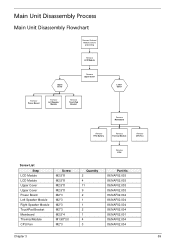
... Remove Left Speaker Module Remove TouchPad Bracket Lower Cover Remove Mainboard Remove RTC Battery Remove Thermal Module Remove CPU Fan Remove CPU Screw List Step LCD Module LCD Module Upper Cover Upper Cover Power Board Left Speaker Module Right Speaker Module TouchPad Bracket Mainboard Thermal Module CPU Fan Screw M2.5*8 M2.5*8 M2...
... Remove Left Speaker Module Remove TouchPad Bracket Lower Cover Remove Mainboard Remove RTC Battery Remove Thermal Module Remove CPU Fan Remove CPU Screw List Step LCD Module LCD Module Upper Cover Upper Cover Power Board Left Speaker Module Right Speaker Module TouchPad Bracket Mainboard Thermal Module CPU Fan Screw M2.5*8 M2.5*8 M2...

Service Guide
Page 70
Remove the two (2) securing screws from all cable clips. 60 Chapter 3 Turn the computer over. Step LCD Module Size M2.5*8 Quantity 2 Screw Type 3. See "Removing the Keyboard" on page 58. 2. Ensure that the cables are free from the bottom of the chassis. Remove the Antenna Cables from the cable channel as shown. Removing the LCD Module 1.
Remove the two (2) securing screws from all cable clips. 60 Chapter 3 Turn the computer over. Step LCD Module Size M2.5*8 Quantity 2 Screw Type 3. See "Removing the Keyboard" on page 58. 2. Ensure that the cables are free from the bottom of the chassis. Remove the Antenna Cables from the cable channel as shown. Removing the LCD Module 1.

Service Guide
Page 71
Stand the computer on the LCD Panel and pull the Antenna cables completely through the chassis. 5. Chapter 3 61 Disconnect the LVDS cable from the cable channel. 4. Remove the cable from the Mainboard. 6.
Stand the computer on the LCD Panel and pull the Antenna cables completely through the chassis. 5. Chapter 3 61 Disconnect the LVDS cable from the cable channel. 4. Remove the cable from the Mainboard. 6.

Service Guide
Page 72
a. Remove the microphone cable. Open the LCD Panel to the full extent to the hinge well. 8. Remove the white Antenna cable from the cable channel. Disconnect the microphone cable on the microphone assembly. Lift the microphone assembly and cable clear of the retaining clips all the way to expose the Hinge Covers. 62 Chapter 3 Ensure that the cable is completely free of the upper cover. b. c. 7. Peel back the foil tab on the upper cover. b a c 9.
a. Remove the microphone cable. Open the LCD Panel to the full extent to the hinge well. 8. Remove the white Antenna cable from the cable channel. Disconnect the microphone cable on the microphone assembly. Lift the microphone assembly and cable clear of the retaining clips all the way to expose the Hinge Covers. 62 Chapter 3 Ensure that the cable is completely free of the upper cover. b. c. 7. Peel back the foil tab on the upper cover. b a c 9.

Service Guide
Page 73
Step LCD Module Size M2.5*8 Quantity 4 13. 10. Press the left and right screw covers from on top of the hinges Screw Type Chapter 3 63 Repeat the process for the right side Hinge Cover. 12. Remove the left side Hinge Cover inward, as shown, and lift to remove the cover from the LCD module. Remove the four (4) securing screws (two each side) from the chassis. 11.
Step LCD Module Size M2.5*8 Quantity 4 13. 10. Press the left and right screw covers from on top of the hinges Screw Type Chapter 3 63 Repeat the process for the right side Hinge Cover. 12. Remove the left side Hinge Cover inward, as shown, and lift to remove the cover from the LCD module. Remove the four (4) securing screws (two each side) from the chassis. 11.
Service Guide
Page 74
14. Lift the LCD Module clear of the Upper Cover. 64 Chapter 3
14. Lift the LCD Module clear of the Upper Cover. 64 Chapter 3

Service Guide
Page 75
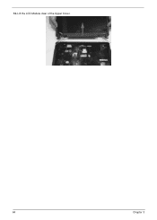
Removing the Upper Cover 1. Turn the computer over . Turn the computer over . Remove the three (3) screw caps at the rear of the Upper Cover as shown. Chapter 3 65 See "Removing the LCD Module" on the bottom panel. Step Upper Cover Size M2.5*8 Quantity 11 Screw Type 3. Remove the eleven (11) screws on page 60. 2.
Removing the Upper Cover 1. Turn the computer over . Turn the computer over . Remove the three (3) screw caps at the rear of the Upper Cover as shown. Chapter 3 65 See "Removing the LCD Module" on the bottom panel. Step Upper Cover Size M2.5*8 Quantity 11 Screw Type 3. Remove the eleven (11) screws on page 60. 2.

Service Guide
Page 91
Chapter 3 81 See "Removing the LCD Module" on page 60. 2. Work along the top edge and down the left side to lift up the outside edges of the bezel. Starting from the bottom edge of the bezel, prying the covers apart. Step LCD Bezel Size M2.5*6 Quantity 4 Screw Type 3. Continue along the right side toward the top of the bezel, pry the bezel upwards and away from the panel. Remove the two (2) upper and two (2) lower bezel screw caps and screws. Removing the LCD Bezel 1. NOTE: If necessary, use a pry to remove the bezel.
Chapter 3 81 See "Removing the LCD Module" on page 60. 2. Work along the top edge and down the left side to lift up the outside edges of the bezel. Starting from the bottom edge of the bezel, prying the covers apart. Step LCD Bezel Size M2.5*6 Quantity 4 Screw Type 3. Continue along the right side toward the top of the bezel, pry the bezel upwards and away from the panel. Remove the two (2) upper and two (2) lower bezel screw caps and screws. Removing the LCD Bezel 1. NOTE: If necessary, use a pry to remove the bezel.

Service Guide
Page 92
Removing the Camera Module 1. Locate the Camera Module at the top of the LCD Module and disconnect the camera cable. 3. See "Removing the LCD Bezel" on page 81. 2. Remove the Camera from the module. 82 Chapter 3
Removing the Camera Module 1. Locate the Camera Module at the top of the LCD Module and disconnect the camera cable. 3. See "Removing the LCD Bezel" on page 81. 2. Remove the Camera from the module. 82 Chapter 3


