Service Guide
Page 7
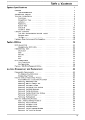
Table of Contents System Specifications 1 Features 1 Optical Media Drive 2 System Block Diagram 5 Your Acer Notebook tour 6 Front View 6 Closed Front View 7 Left View 7 Right View 9 Bottom View 9 Indicators 10 TouchPad Basics 11 ...DOS Flash Utility 32 WinFlash Utility 34 Remove HDD/BIOS Password Utilities 35 Machine Disassembly and Replacement 43 Disassembly Requirements 43 Pre-disassembly Instructions 44 Disassembly Process 44 External Module Disassembly Process 45 External Modules Disassembly Flowchart 45 Removing the Battery Pack 46 Removing the SD Dummy Card 47 ...
Table of Contents System Specifications 1 Features 1 Optical Media Drive 2 System Block Diagram 5 Your Acer Notebook tour 6 Front View 6 Closed Front View 7 Left View 7 Right View 9 Bottom View 9 Indicators 10 TouchPad Basics 11 ...DOS Flash Utility 32 WinFlash Utility 34 Remove HDD/BIOS Password Utilities 35 Machine Disassembly and Replacement 43 Disassembly Requirements 43 Pre-disassembly Instructions 44 Disassembly Process 44 External Module Disassembly Process 45 External Modules Disassembly Flowchart 45 Removing the Battery Pack 46 Removing the SD Dummy Card 47 ...
Service Guide
Page 8
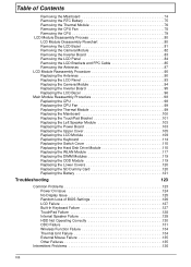
... Mainboard 74 Removing the RTC Battery 75 Removing the Thermal Module 76 Removing the CPU Fan 78 Removing the CPU 79 LCD Module Disassembly Process 80 LCD Module Disassembly Flowchart 80 Removing the LCD Bezel 81 Removing the Camera Module 82 Removing the Inverter Board 83 Removing the LCD Panel 84 Removing...
... Mainboard 74 Removing the RTC Battery 75 Removing the Thermal Module 76 Removing the CPU Fan 78 Removing the CPU 79 LCD Module Disassembly Process 80 LCD Module Disassembly Flowchart 80 Removing the LCD Bezel 81 Removing the Camera Module 82 Removing the Inverter Board 83 Removing the LCD Panel 84 Removing...
Service Guide
Page 53
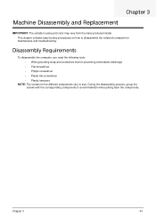
...-by-step procedures on how to avoid mismatch when putting back the components. During the disassembly process, group the screws with the corresponding components to disassemble the notebook computer for the different components vary in size. Disassembly Requirements To disassemble the computer, you need the following tools: • Wrist grounding strap and conductive mat...
...-by-step procedures on how to avoid mismatch when putting back the components. During the disassembly process, group the screws with the corresponding components to disassemble the notebook computer for the different components vary in size. Disassembly Requirements To disassemble the computer, you need the following tools: • Wrist grounding strap and conductive mat...
Service Guide
Page 54
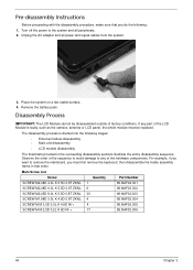
..., antenna or LCD panel, the whole module must first remove the keyboard, then disassemble the inside assembly frame in the succeeding disassembly sections illustrate the entire disassembly sequence. Turn off the power to the system and all power and signal cables ... the mainboard, you do the following stages: • External module disassembly • Main unit disassembly • LCD module disassembly The flowcharts provided in that you must be disassembled outside of factory conditions. Disassembly Process IMPORTANT: The LCD Module cannot be replaced. Place the system ...
..., antenna or LCD panel, the whole module must first remove the keyboard, then disassemble the inside assembly frame in the succeeding disassembly sections illustrate the entire disassembly sequence. Turn off the power to the system and all power and signal cables ... the mainboard, you do the following stages: • External module disassembly • Main unit disassembly • LCD module disassembly The flowcharts provided in that you must be disassembled outside of factory conditions. Disassembly Process IMPORTANT: The LCD Module cannot be replaced. Place the system ...
Service Guide
Page 55
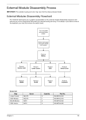
... The flowchart below gives you a graphic representation of the external module disassembly sequence and instructs you must first remove the switch board. Turn off system and peripherals power Disconnect power and signal cables from the mass produced ...model. For example, if you want to remove the keyboard, you on the components that need to be removed during servicing. External Module Disassembly Process IMPORTANT: The outside housing and color may vary from system Remove Battery Remove Dummy Card Remove Lower Covers Remove ODD Remove Switch Cover Remove...
... The flowchart below gives you a graphic representation of the external module disassembly sequence and instructs you must first remove the switch board. Turn off system and peripherals power Disconnect power and signal cables from the mass produced ...model. For example, if you want to remove the keyboard, you on the components that need to be removed during servicing. External Module Disassembly Process IMPORTANT: The outside housing and color may vary from system Remove Battery Remove Dummy Card Remove Lower Covers Remove ODD Remove Switch Cover Remove...
Service Guide
Page 69
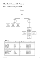
Main Unit Disassembly Process Main Unit Disassembly Flowchart Remove External Modules before proceeding Remove LCD Module Upper Cover Remove Upper Cover Remove Power Board Remove Left Speaker Module Remove TouchPad Bracket Lower ...
Main Unit Disassembly Process Main Unit Disassembly Flowchart Remove External Modules before proceeding Remove LCD Module Upper Cover Remove Upper Cover Remove Power Board Remove Left Speaker Module Remove TouchPad Bracket Lower ...
Service Guide
Page 135
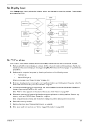
If the POST or video appears on the external display, see "Disassembly Process" on page 124. 3. Disconnect power and all external devices including port replicators or docking stations. Chapter 4 125 No Display Issue If the Display doesn't ...
If the POST or video appears on the external display, see "Disassembly Process" on page 124. 3. Disconnect power and all external devices including port replicators or docking stations. Chapter 4 125 No Display Issue If the Display doesn't ...
Service Guide
Page 136
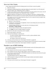
...NOTE: Ensure that : • The device is correctly configured: a. b. d. See the User Manual for instructions on page 44. 5. See "Disassembly Process" on adjusting settings. Check the Device Manager to determine that the computer is still not resolved, see "Online Support Information" on battery alone...at the highest brightness setting, the LCD is faulty and should be replaced. e. Click Apply and check the display. See "Disassembly Process" on the screen), the LCD is faulty and should be replaced. If extensive pixel damage is only abnormal in an ...
...NOTE: Ensure that : • The device is correctly configured: a. b. d. See the User Manual for instructions on page 44. 5. See "Disassembly Process" on adjusting settings. Check the Device Manager to determine that the computer is still not resolved, see "Online Support Information" on battery alone...at the highest brightness setting, the LCD is faulty and should be replaced. e. Click Apply and check the display. See "Disassembly Process" on the screen), the LCD is faulty and should be replaced. If extensive pixel damage is only abnormal in an ...
Service Guide
Page 140
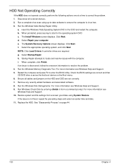
... System Recovery Options screen displays. NOTE: Click Load Drivers if controller drives are set as the first boot device on page 44. 130 Chapter 4 See "Disassembly Process" on the Boot menu. 6. Run the Windows Vista Startup Repair Utility: a. Select the appropriate operating system, and click Next. Remove any key to start...
... System Recovery Options screen displays. NOTE: Click Load Drivers if controller drives are set as the first boot device on page 44. 130 Chapter 4 See "Disassembly Process" on the Boot menu. 6. Run the Windows Vista Startup Repair Utility: a. Select the appropriate operating system, and click Next. Remove any key to start...
Service Guide
Page 143
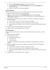
.... Check for bent or broken pins on the Information page. Try an alternate cable, if available. Retry reading the CD or DVD. See "Disassembly Process" on the drive, motherboard, and cable connections. If the drive works with the new cable, the original cable should be replaced. 4. ...the ODDs specified in the drive, perform the following actions one at a time to correct the problem. 1. Check for the other discs. b. See "Disassembly Process" on page 44. d. Try an alternate cable, if available. Chapter 4 133 NOTE: Check that the Enable DMA box is probably defective and...
.... Check for bent or broken pins on the Information page. Try an alternate cable, if available. Retry reading the CD or DVD. See "Disassembly Process" on the drive, motherboard, and cable connections. If the drive works with the new cable, the original cable should be replaced. 4. ...the ODDs specified in the drive, perform the following actions one at a time to correct the problem. 1. Check for the other discs. b. See "Disassembly Process" on page 44. d. Try an alternate cable, if available. Chapter 4 133 NOTE: Check that the Enable DMA box is probably defective and...
Service Guide
Page 245
... 79 Replacing 98 CPU Fan Removing 78 Index Replacing 99 D DIMM Modules Removing 51 Replacing 119 Display 5 display hotkeys 14 E EasyTouch Failure 134 External Module Disassembly Flowchart 45 F Features 1 Flash Utility 31 FPC Cable Removing 85 FRU (Field Replaceable Unit) List 151 H Hard Disk Drive Removing 55 Replacing 115 HDTV Switch...
... 79 Replacing 98 CPU Fan Removing 78 Index Replacing 99 D DIMM Modules Removing 51 Replacing 119 Display 5 display hotkeys 14 E EasyTouch Failure 134 External Module Disassembly Flowchart 45 F Features 1 Flash Utility 31 FPC Cable Removing 85 FRU (Field Replaceable Unit) List 151 H Hard Disk Drive Removing 55 Replacing 115 HDTV Switch...
Service Guide
Page 246
...81 Replacing 96 LCD Brackets Removing 85 Replacing 93 LCD Cable Replacing 93 LCD Failure 127 LCD Module Removing 60 Replacing 109 LCD Module Disassembly Flowchart 80 LCD Module Reassembly Procedure 90 LCD Panel Removing 83, 84, 95 Replacing 93 Left Speaker Module Removing 70 Replacing 103 Lower... Covers Removing 48 Replacing 120 M Main Unit Disassembly Flowchart 59 Mainboard Removing 74 Replacing 100 media access on indicator 10 Memory Removing 51 Replacing 119 Memory Check 124 Model Definition 164 N No...
...81 Replacing 96 LCD Brackets Removing 85 Replacing 93 LCD Cable Replacing 93 LCD Failure 127 LCD Module Removing 60 Replacing 109 LCD Module Disassembly Flowchart 80 LCD Module Reassembly Procedure 90 LCD Panel Removing 83, 84, 95 Replacing 93 Left Speaker Module Removing 70 Replacing 103 Lower... Covers Removing 48 Replacing 120 M Main Unit Disassembly Flowchart 59 Mainboard Removing 74 Replacing 100 media access on indicator 10 Memory Removing 51 Replacing 119 Memory Check 124 Model Definition 164 N No...


