Quick Start Guide
Page 6
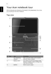
Delivers audio output. Top view 1 2 3 11 10 9 4 5 6 # Icon 1 2 3 Item Acer Crystal Eye webcam Display screen Speaker 8 7 Description Web camera for video communication. (only for certain models) Also called Liquid-Crystal Display (LCD), displays computer output (configuration may vary by models). English 4 Your Acer notebook tour After setting up your computer as illustrated in the setup poster, let us show you around your new Acer notebook.
Delivers audio output. Top view 1 2 3 11 10 9 4 5 6 # Icon 1 2 3 Item Acer Crystal Eye webcam Display screen Speaker 8 7 Description Web camera for video communication. (only for certain models) Also called Liquid-Crystal Display (LCD), displays computer output (configuration may vary by models). English 4 Your Acer notebook tour After setting up your computer as illustrated in the setup poster, let us show you around your new Acer notebook.

Quick Start Guide
Page 9
... Secure Digital (SD), MultiMediaCard (MMC), Memory Stick (MS), Memory Stick PRO (MS PRO), xDPicture Card (xD). Headphone/speaker/ Connects to USB 2.0 devices (e.g., USB mouse, USB camera). Left view # Icon 1 2 3 4 5 12 3 Item DC-in jack 4 5 Description Connects to an Ethernet 10/100-based network. Ethernet (RJ-45) port Connects to an AC...
... Secure Digital (SD), MultiMediaCard (MMC), Memory Stick (MS), Memory Stick PRO (MS PRO), xDPicture Card (xD). Headphone/speaker/ Connects to USB 2.0 devices (e.g., USB mouse, USB camera). Left view # Icon 1 2 3 4 5 12 3 Item DC-in jack 4 5 Description Connects to an Ethernet 10/100-based network. Ethernet (RJ-45) port Connects to an AC...
Service Guide
Page 8
... CPU Fan 78 Removing the CPU 79 LCD Module Disassembly Process 80 LCD Module Disassembly Flowchart 80 Removing the LCD Bezel 81 Removing the Camera Module 82 Removing the Inverter Board 83 Removing the LCD Panel 84 Removing the LCD Brackets and FPC Cable 85 Removing the Antennas 87 ...LCD Module Reassembly Procedure 90 Replacing the Antennas 90 Replacing the LCD Panel 93 Replacing the Camera Module 94 Replacing the Inverter Board 95 Replacing the LCD Bezel 96 Main Module Reassembly Procedure 98 Replacing the CPU 98 Replacing the CPU ...
... CPU Fan 78 Removing the CPU 79 LCD Module Disassembly Process 80 LCD Module Disassembly Flowchart 80 Removing the LCD Bezel 81 Removing the Camera Module 82 Removing the Inverter Board 83 Removing the LCD Panel 84 Removing the LCD Brackets and FPC Cable 85 Removing the Antennas 87 ...LCD Module Reassembly Procedure 90 Replacing the Antennas 90 Replacing the LCD Panel 93 Replacing the Camera Module 94 Replacing the Inverter Board 95 Replacing the LCD Bezel 96 Main Module Reassembly Procedure 98 Replacing the CPU 98 Replacing the CPU ...
Service Guide
Page 16
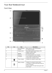
.... Battery indicator Indicates the computer's battery status. 1. Chapter 1 For entering data into your computer. Your Acer Notebook tour Front View No. 1 2 3 4 5 6 6 Icon Item Acer Crystal Eye webcam Display screen Speaker Keyboard Touchpad Power indicator Description Web camera for video communication (for selected models). Charging: The light shows amber when the battery is charging...
.... Battery indicator Indicates the computer's battery status. 1. Chapter 1 For entering data into your computer. Your Acer Notebook tour Front View No. 1 2 3 4 5 6 6 Icon Item Acer Crystal Eye webcam Display screen Speaker Keyboard Touchpad Power indicator Description Web camera for video communication (for selected models). Charging: The light shows amber when the battery is charging...

Service Guide
Page 18
Connect to an Ethernet 10/100-based network. speakers, headphones). 8 Chapter 1 No. 2 3 4 5 Icon Item Ethernet (RJ-45) port External display (VGA) port USB 2.0 ports Microphone-in jack Headphones/ speaker/line-out jack Description Connects to USB 2.0 devices (e.g. Connects to audio line-out devices (e.g. USB mouse, USB camera). Connects to a display device (e.g. external monitor, LCD projector). Accepts input from external microphones.
Connect to an Ethernet 10/100-based network. speakers, headphones). 8 Chapter 1 No. 2 3 4 5 Icon Item Ethernet (RJ-45) port External display (VGA) port USB 2.0 ports Microphone-in jack Headphones/ speaker/line-out jack Description Connects to USB 2.0 devices (e.g. Connects to audio line-out devices (e.g. USB mouse, USB camera). Connects to a display device (e.g. external monitor, LCD projector). Accepts input from external microphones.
Service Guide
Page 54
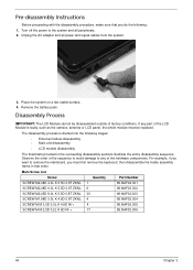
... in that you must be disassembled outside of factory conditions. Place the system on a flat, stable surface. 4. The disassembly process is faulty, such as the camera, antenna or LCD panel, the whole module must first remove the keyboard, then disassemble the inside assembly frame in the succeeding disassembly sections illustrate the...
... in that you must be disassembled outside of factory conditions. Place the system on a flat, stable surface. 4. The disassembly process is faulty, such as the camera, antenna or LCD panel, the whole module must first remove the keyboard, then disassemble the inside assembly frame in the succeeding disassembly sections illustrate the...

Service Guide
Page 92
Locate the Camera Module at the top of the LCD Module and disconnect the camera cable. 3. Remove the Camera from the module. 82 Chapter 3 Removing the Camera Module 1. See "Removing the LCD Bezel" on page 81. 2.
Locate the Camera Module at the top of the LCD Module and disconnect the camera cable. 3. Remove the Camera from the module. 82 Chapter 3 Removing the Camera Module 1. See "Removing the LCD Bezel" on page 81. 2.

Service Guide
Page 94
Step LCD Panel Size M2.5*6 Quantity 2 3. Pull up on page 82. 2. Lift the LCD Panel clear of the module. 84 Chapter 3 Removing the LCD Panel 1. Screw Type 4. See "Removing the Camera Module" on the cable to free it from the LCD Panel. Remove the two (2) securing screws from the adhesive.
Step LCD Panel Size M2.5*6 Quantity 2 3. Pull up on page 82. 2. Lift the LCD Panel clear of the module. 84 Chapter 3 Removing the LCD Panel 1. Screw Type 4. See "Removing the Camera Module" on the cable to free it from the LCD Panel. Remove the two (2) securing screws from the adhesive.

Service Guide
Page 104
Connect the cable to the camera module. 94 Chapter 3 Place the camera in the LCD Module. 2. Secure the LCD module with the two (2) securing screws. Replacing the Camera Module 1. 5.
Connect the cable to the camera module. 94 Chapter 3 Place the camera in the LCD Module. 2. Secure the LCD module with the two (2) securing screws. Replacing the Camera Module 1. 5.

Service Guide
Page 164
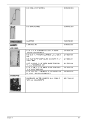
LCD Assembly 1 2 3 6 7 8 4 9 5 No. Description 1 LCD Bezel 2 Antenna (Main) Antenna (Aux) 3 LCD Brackets 4 LCD Cable 5 LCD Cover 6 Hinge 7 LCD Sponge 8 Camera 0.3M 9 Inverter Acer P/N 60.NAF02.005 50.NAF02.002 50.NAF02.003 33.NAF02.005 50.NAF02.004 60.NAF02.004 N/A N/A 57.NAE02.001 19.NAF02.001 154 Chapter 6
LCD Assembly 1 2 3 6 7 8 4 9 5 No. Description 1 LCD Bezel 2 Antenna (Main) Antenna (Aux) 3 LCD Brackets 4 LCD Cable 5 LCD Cover 6 Hinge 7 LCD Sponge 8 Camera 0.3M 9 Inverter Acer P/N 60.NAF02.005 50.NAF02.002 50.NAF02.003 33.NAF02.005 50.NAF02.004 60.NAF02.004 N/A N/A 57.NAE02.001 19.NAF02.001 154 Chapter 6
Service Guide
Page 171
LCD CABLE FOR W/CMOS 50.NAF02.004 LCD BRACKET R&L 33.NAF02.005 LCD PANEL MAINBOARD INVERTER CAMERA 0.3M 19.NAF02.001 57.NAE02.001 CCFL LCD LPL 15.6"W WXGA Glare LP156WH1TLA3 LF 220nit 8ms 400:1 LCD CMO 15.6" WXGA Glare N156B3-L02 ... LF 200NIT 10MS 500:1 (LOW COST) LK.15608.006 LK.1560D.001 LK.15605.001 LK.15605.002 LK.15605.014 LK.1560D.013 MAINBOARD ASPIRE 5334 INTEL GL40 ICH9M LF WITH ALL CONNECTORS MB.PVS02.001 Chapter 6 161
LCD CABLE FOR W/CMOS 50.NAF02.004 LCD BRACKET R&L 33.NAF02.005 LCD PANEL MAINBOARD INVERTER CAMERA 0.3M 19.NAF02.001 57.NAE02.001 CCFL LCD LPL 15.6"W WXGA Glare LP156WH1TLA3 LF 220nit 8ms 400:1 LCD CMO 15.6" WXGA Glare N156B3-L02 ... LF 200NIT 10MS 500:1 (LOW COST) LK.15608.006 LK.1560D.001 LK.15605.001 LK.15605.002 LK.15605.014 LK.1560D.013 MAINBOARD ASPIRE 5334 INTEL GL40 ICH9M LF WITH ALL CONNECTORS MB.PVS02.001 Chapter 6 161
Service Guide
Page 245
... Navigating 23 Onboard Device Configuration 27 Power 29 Save and Exit 30 Security 26 System Security 30 Board Layout Top View 145 brightness hotkeys 14 C Camera Module Removing 82 Replacing 94 caps lock on indicator 7, 10 Common Problems 124 computer on indicator 10 CPU Removing 79 Replacing 98 CPU Fan Removing...
... Navigating 23 Onboard Device Configuration 27 Power 29 Save and Exit 30 Security 26 System Security 30 Board Layout Top View 145 brightness hotkeys 14 C Camera Module Removing 82 Replacing 94 caps lock on indicator 7, 10 Common Problems 124 computer on indicator 10 CPU Removing 79 Replacing 98 CPU Fan Removing...


