Quick Start Guide
Page 5
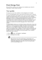
The Aspire Series Generic User Guide contains useful information applying to complete the installation. The Quick Guide introduces you to the basic features and functions of your mobile computing needs. This guide contains detailed information on how to use your Acer notebook, we have designed a set ... productive, please refer to functions or features which are marked in the model you get started with language such as using the keyboard and audio, etc. Follow these steps to access it contains warranty information and the general regulations and safety notices for certain models...
The Aspire Series Generic User Guide contains useful information applying to complete the installation. The Quick Guide introduces you to the basic features and functions of your mobile computing needs. This guide contains detailed information on how to use your Acer notebook, we have designed a set ... productive, please refer to functions or features which are marked in the model you get started with language such as using the keyboard and audio, etc. Follow these steps to access it contains warranty information and the general regulations and safety notices for certain models...
Quick Start Guide
Page 7
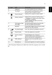
Charging: The light shows amber when the battery is active. 11 Microphone Internal microphone for your computer. 5 English # Icon 4 5 6 Item Keyboard Touchpad Power indicator1 Description For entering data into your hands when you use the computer. 9 Touchpad toggle Turns the internal touchpad on and off . Fully ...
Charging: The light shows amber when the battery is active. 11 Microphone Internal microphone for your computer. 5 English # Icon 4 5 6 Item Keyboard Touchpad Power indicator1 Description For entering data into your hands when you use the computer. 9 Touchpad toggle Turns the internal touchpad on and off . Fully ...
Service Guide
Page 7
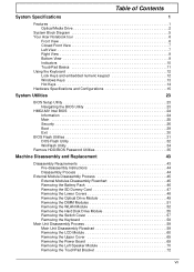
... System Specifications 1 Features 1 Optical Media Drive 2 System Block Diagram 5 Your Acer Notebook tour 6 Front View 6 Closed Front View 7 Left View 7 Right View 9 Bottom View 9 Indicators 10 TouchPad Basics 11 Using the Keyboard 12 Lock Keys and embedded numeric keypad 12 Windows Keys 13 Hot Keys 14 ... DIMM Modules 51 Removing the WLAN Module 52 Removing the Hard Disk Drive Module 55 Removing the Switch Cover 57 Removing the Keyboard 58 Main Unit Disassembly Process 59 Main Unit Disassembly Flowchart 59 Removing the LCD Module 60 Removing the Upper Cover 65 Removing...
... System Specifications 1 Features 1 Optical Media Drive 2 System Block Diagram 5 Your Acer Notebook tour 6 Front View 6 Closed Front View 7 Left View 7 Right View 9 Bottom View 9 Indicators 10 TouchPad Basics 11 Using the Keyboard 12 Lock Keys and embedded numeric keypad 12 Windows Keys 13 Hot Keys 14 ... DIMM Modules 51 Removing the WLAN Module 52 Removing the Hard Disk Drive Module 55 Removing the Switch Cover 57 Removing the Keyboard 58 Main Unit Disassembly Process 59 Main Unit Disassembly Flowchart 59 Removing the LCD Module 60 Removing the Upper Cover 65 Removing...
Service Guide
Page 8
... Replacing the Left Speaker Module 103 Replacing the Power Board 103 Replacing the Upper Cover 105 Replacing the LCD Module 109 Replacing the Keyboard 114 Replacing the Switch Cover 115 Replacing the Hard Disk Drive Module 115 Replacing the WLAN Module 117 Replacing the DIMM Modules 119 ... 123 Common Problems 123 Power On Issue 124 No Display Issue 125 Random Loss of BIOS Settings 126 LCD Failure 127 Built-In Keyboard Failure 127 TouchPad Failure 128 Internal Speaker Failure 128 HDD Not Operating Correctly 130 ODD Failure 131 Wireless Function Failure 134 Thermal Unit ...
... Replacing the Left Speaker Module 103 Replacing the Power Board 103 Replacing the Upper Cover 105 Replacing the LCD Module 109 Replacing the Keyboard 114 Replacing the Switch Cover 115 Replacing the Hard Disk Drive Module 115 Replacing the WLAN Module 117 Replacing the DIMM Modules 119 ... 123 Common Problems 123 Power On Issue 124 No Display Issue 125 Random Loss of BIOS Settings 126 LCD Failure 127 Built-In Keyboard Failure 127 TouchPad Failure 128 Internal Speaker Failure 128 HDD Not Operating Correctly 130 ODD Failure 131 Wireless Function Failure 134 Thermal Unit ...
Service Guide
Page 13
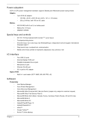
...; keys, independent numeric keypad, international language support • Easy-launch keys: touchpad lock, communication • Media control keys (printed on keyboard): play/pause, stop, previous, next I/O interface • Two USB 2.0 ports • External display (VGA) port • Headphone/speaker...RJ-45) port • DC-in jack for AC adapter Aspire 5734Z • Multi-in-1 card reader (SD™, MMC, MS, MS PRO, xD) Software Productivity • Acer Backup Manager • Acer ePower Management • Acer eRecovery Management • Microsoft® Office Personal 2007 (Service...
...; keys, independent numeric keypad, international language support • Easy-launch keys: touchpad lock, communication • Media control keys (printed on keyboard): play/pause, stop, previous, next I/O interface • Two USB 2.0 ports • External display (VGA) port • Headphone/speaker...RJ-45) port • DC-in jack for AC adapter Aspire 5734Z • Multi-in-1 card reader (SD™, MMC, MS, MS PRO, xD) Software Productivity • Acer Backup Manager • Acer ePower Management • Acer eRecovery Management • Microsoft® Office Personal 2007 (Service...
Service Guide
Page 16
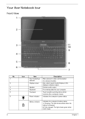
.... Charging: The light shows amber when the battery is charging. 2. For entering data into your computer. Indicates the computer's power status. Your Acer Notebook tour Front View No. 1 2 3 4 5 6 6 Icon Item Acer Crystal Eye webcam Display screen Speaker Keyboard Touchpad Power indicator Description Web camera for video communication (for selected models). Delivers audio output.
.... Charging: The light shows amber when the battery is charging. 2. For entering data into your computer. Indicates the computer's power status. Your Acer Notebook tour Front View No. 1 2 3 4 5 6 6 Icon Item Acer Crystal Eye webcam Display screen Speaker Keyboard Touchpad Power indicator Description Web camera for video communication (for selected models). Delivers audio output.
Service Guide
Page 22
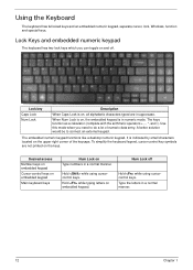
...uppercase. Hold while typing letters on Type numbers in a normal manner. 12 Chapter 1 Num Lock off . Lock Keys and embedded numeric keypad The keyboard has two lock keys which you need to connect an external keypad. A better solution would be to do a lot of the keycaps. Type ...the letters in a normal manner. Desired access Number keys on embedded keypad Cursor-control keys on embedded keypad Main keyboard keys Num Lock on embedded keypad. Lock key Caps Lock Num Lock Description When Caps Lock is on, all alphabetic characters typed are not ...
...uppercase. Hold while typing letters on Type numbers in a normal manner. 12 Chapter 1 Num Lock off . Lock Keys and embedded numeric keypad The keyboard has two lock keys which you need to connect an external keypad. A better solution would be to do a lot of the keycaps. Type ...the letters in a normal manner. Desired access Number keys on embedded keypad Cursor-control keys on embedded keypad Main keyboard keys Num Lock on embedded keypad. Lock key Caps Lock Num Lock Description When Caps Lock is on, all alphabetic characters typed are not ...
Service Guide
Page 23
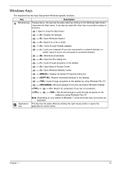
... Flip 3-D Note: Depending on the Windows Start button; it launches the Start menu. Application This key has the same effect as described. Windows Keys The keyboard has two keys that perform Windows-specific functions. Key Description Windows key Pressed alone, this key has the same effect as clicking on your edition...
... Flip 3-D Note: Depending on the Windows Start button; it launches the Start menu. Application This key has the same effect as described. Windows Keys The keyboard has two keys that perform Windows-specific functions. Key Description Windows key Pressed alone, this key has the same effect as clicking on your edition...
Service Guide
Page 30
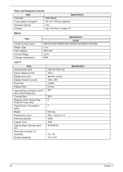
... x 900 0.2388 Normal 220 600:1 8 7 580 max. 398.1 x 232.8 x 5.5 LVDS 262K 20/45/45/45 0 to +50 -20 to +60 Specification 20 Chapter 1 Power and Keyboard Controller Item Controller Total number of keypads Specification ENE KB926 99-/100-/103-key...
... x 900 0.2388 Normal 220 600:1 8 7 580 max. 398.1 x 232.8 x 5.5 LVDS 262K 20/45/45/45 0 to +50 -20 to +60 Specification 20 Chapter 1 Power and Keyboard Controller Item Controller Total number of keypads Specification ENE KB926 99-/100-/103-key...
Service Guide
Page 54
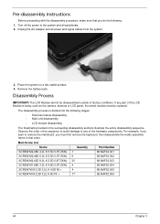
... order of the hardware components. The disassembly process is faulty, such as the camera, antenna or LCD panel, the whole module must first remove the keyboard, then disassemble the inside assembly frame in that you must be disassembled outside of the LCD Module is divided into the following : 1. For example, if...
... order of the hardware components. The disassembly process is faulty, such as the camera, antenna or LCD panel, the whole module must first remove the keyboard, then disassemble the inside assembly frame in that you must be disassembled outside of the LCD Module is divided into the following : 1. For example, if...
Service Guide
Page 55
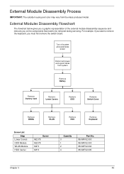
... color may vary from system Remove Battery Remove Dummy Card Remove Lower Covers Remove ODD Remove Switch Cover Remove DIMMs Remove WLAN Remove HDD Remove Keyboard Screw List Step Lower Covers ODD Module WLAN Module HDD Carrier Screw M2.5*8 M2.5*8 M2*3 M3*3 Quantity 3 1 2 4 Part No.... 86.NAF02.003 86.NAF02.003 86.NAF02.004 86.NAF02.005 Chapter 3 45 For example, if you want to remove the keyboard, you on the components that need to be removed during servicing. External Modules Disassembly Flowchart The flowchart below gives you a graphic representation of the ...
... color may vary from system Remove Battery Remove Dummy Card Remove Lower Covers Remove ODD Remove Switch Cover Remove DIMMs Remove WLAN Remove HDD Remove Keyboard Screw List Step Lower Covers ODD Module WLAN Module HDD Carrier Screw M2.5*8 M2.5*8 M2*3 M3*3 Quantity 3 1 2 4 Part No.... 86.NAF02.003 86.NAF02.003 86.NAF02.004 86.NAF02.005 Chapter 3 45 For example, if you want to remove the keyboard, you on the components that need to be removed during servicing. External Modules Disassembly Flowchart The flowchart below gives you a graphic representation of the ...
Service Guide
Page 67
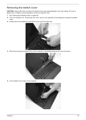
... expose the plastic locks. 3. Gently insert a thin plastic pry and lift the cover up the cover as shown. 5. Lift the Switch Cover clear of the Keyboard to the outer casing.
... expose the plastic locks. 3. Gently insert a thin plastic pry and lift the cover up the cover as shown. 5. Lift the Switch Cover clear of the Keyboard to the outer casing.

Service Guide
Page 68
Lift the keyboard clear of the Keyboard and rotate it upward away from the mainboard. 5. Open the locking latch and disconnect the FFC from the Upper Cover. 3. See "Removing the Switch Cover" on to the TouchPad area to expose the FFC connector. 4. Removing the Keyboard 1. Turn the keyboard over on page 57. 2. Pry up the centre of the Upper Cover. 58 Chapter 3
Lift the keyboard clear of the Keyboard and rotate it upward away from the mainboard. 5. Open the locking latch and disconnect the FFC from the Upper Cover. 3. See "Removing the Switch Cover" on to the TouchPad area to expose the FFC connector. 4. Removing the Keyboard 1. Turn the keyboard over on page 57. 2. Pry up the centre of the Upper Cover. 58 Chapter 3

Service Guide
Page 70
Step LCD Module Size M2.5*8 Quantity 2 Screw Type 3. Turn the computer over. Remove the two (2) securing screws from the cable channel as shown. Remove the Antenna Cables from the bottom of the chassis. Ensure that the cables are free from all cable clips. 60 Chapter 3 Removing the LCD Module 1. See "Removing the Keyboard" on page 58. 2.
Step LCD Module Size M2.5*8 Quantity 2 Screw Type 3. Turn the computer over. Remove the two (2) securing screws from the cable channel as shown. Remove the Antenna Cables from the bottom of the chassis. Ensure that the cables are free from all cable clips. 60 Chapter 3 Removing the LCD Module 1. See "Removing the Keyboard" on page 58. 2.
Service Guide
Page 124
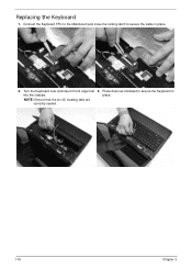
Press down as indicated to secure the cable in place. 114 Chapter 3 Connect the Keyboard FFC to the Mainboard and close the locking latch to secure the Keyboard in place. 2. NOTE: Ensure that the six (6) locating tabs are correctly seated. 3. Turn the Keyboard over and insert it front edge first into the chassis. Replacing the Keyboard 1.
Press down as indicated to secure the cable in place. 114 Chapter 3 Connect the Keyboard FFC to the Mainboard and close the locking latch to secure the Keyboard in place. 2. NOTE: Ensure that the six (6) locating tabs are correctly seated. 3. Turn the Keyboard over and insert it front edge first into the chassis. Replacing the Keyboard 1.
Service Guide
Page 133
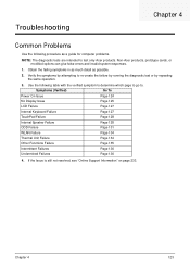
... Chapter 4 123 Symptoms (Verified) Go To Power On Issue Page 124 No Display Issue Page 125 LCD Failure Page 127 Internal Keyboard Failure Page 127 TouchPad Failure Page 128 Internal Speaker Failure Page 128 ODD Failure Page 131 WLAN Failure Page 134 Thermal Unit Failure ... Obtain the failing symptoms in as much detail as a guide for computer problems. NOTE: The diagnostic tests are intended to test only Acer products. Verify the symptoms by attempting to re-create the failure by running the diagnostic test or by repeating the same operation. 3. Troubleshooting...
... Chapter 4 123 Symptoms (Verified) Go To Power On Issue Page 124 No Display Issue Page 125 LCD Failure Page 127 Internal Keyboard Failure Page 127 TouchPad Failure Page 128 Internal Speaker Failure Page 128 ODD Failure Page 131 WLAN Failure Page 134 Thermal Unit Failure ... Obtain the failing symptoms in as much detail as a guide for computer problems. NOTE: The diagnostic tests are intended to test only Acer products. Verify the symptoms by attempting to re-create the failure by running the diagnostic test or by repeating the same operation. 3. Troubleshooting...
Service Guide
Page 137
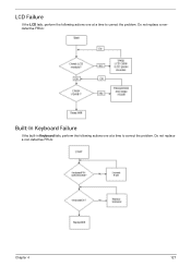
LCD Failure If the LCD fails, perform the following actions one at a time to correct the problem. Do not replace a nondefective FRUs: Built-In Keyboard Failure If the built-in Keyboard fails, perform the following actions one at a time to correct the problem. Do not replace a non-defective FRUs: Chapter 4 127
LCD Failure If the LCD fails, perform the following actions one at a time to correct the problem. Do not replace a nondefective FRUs: Built-In Keyboard Failure If the built-in Keyboard fails, perform the following actions one at a time to correct the problem. Do not replace a non-defective FRUs: Chapter 4 127
Service Guide
Page 149
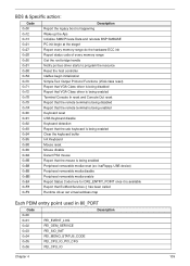
... Out reset Report that the remote terminal is being disabled Report that the remote terminal is being enabled Keyboard reset USB Keyboard disable Keyboard detection Report that the usb keyboard is being enabled Clear the keyboard buffer Init Keyboard Mouse reset Mouse disable Detect PS2 mouse Report that the mouse is being enabled Peripheral removable media...
... Out reset Report that the remote terminal is being disabled Report that the remote terminal is being enabled Keyboard reset USB Keyboard disable Keyboard detection Report that the usb keyboard is being enabled Clear the keyboard buffer Init Keyboard Mouse reset Mouse disable Detect PS2 mouse Report that the mouse is being enabled Peripheral removable media...
Service Guide
Page 155
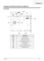
Jumper and Connector Locations Top View Chapter 5 Item JLVDS1 JP14 JSPK1 JMIC2 JKB1 JTP1 U11 SW4 SW3 JMIC2 Description LCD Connector Power/B Connector Speaker(Left) Connector Microphone Connector Internal Keyboard Connector for 15.6" Touch Pad Connector South Bridge Touch pad (Left) Button for 15.6" Touch pad (Right) Button for 15.6" Internal analog MIC Chapter 5 145
Jumper and Connector Locations Top View Chapter 5 Item JLVDS1 JP14 JSPK1 JMIC2 JKB1 JTP1 U11 SW4 SW3 JMIC2 Description LCD Connector Power/B Connector Speaker(Left) Connector Microphone Connector Internal Keyboard Connector for 15.6" Touch Pad Connector South Bridge Touch pad (Left) Button for 15.6" Touch pad (Right) Button for 15.6" Internal analog MIC Chapter 5 145
Service Guide
Page 168
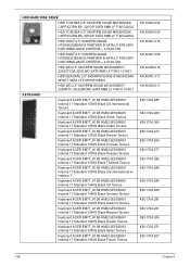
... WD5000BEVT22A0RT0, ML320M,WD SATA 8MB LF F/W:01.01A01 KEYBOARD Keyboard ACER EM7T_A10B HM52/JE50/BA51 Internal 17 Standard 103KS Black US International Texture Keyboard ACER EM7T_A10B HM52/JE50/BA51 Internal 17 Standard 103KS Black Greek Texture Keyboard ACER EM7T_A10B HM52/JE50/BA51 Internal 17 Standard 103KS Black Arabic Texture Keyboard ACER EM7T_A10B HM52/JE50/BA51 Internal 17 Standard 103KS...
... WD5000BEVT22A0RT0, ML320M,WD SATA 8MB LF F/W:01.01A01 KEYBOARD Keyboard ACER EM7T_A10B HM52/JE50/BA51 Internal 17 Standard 103KS Black US International Texture Keyboard ACER EM7T_A10B HM52/JE50/BA51 Internal 17 Standard 103KS Black Greek Texture Keyboard ACER EM7T_A10B HM52/JE50/BA51 Internal 17 Standard 103KS Black Arabic Texture Keyboard ACER EM7T_A10B HM52/JE50/BA51 Internal 17 Standard 103KS...


