
Aspire 5330/5730Z Quick Guide
Page 11
Note: Do not cover or obstruct the opening of the fan. English 11 Base view 1 6 2 3 4 5 # Icon Item 1 Battery bay Description Houses the computer's battery pack. 2 Battery lock Locks the battery in position. 3 Battery release latch Releases the battery for removal. 4 Memory compartment Houses the computer's main memory. 5 Hard disk bay Houses the computer's hard disk (secured with screws). 6 Ventilation slots and Enable the computer to stay cool, even cooling fan after prolonged use.
Note: Do not cover or obstruct the opening of the fan. English 11 Base view 1 6 2 3 4 5 # Icon Item 1 Battery bay Description Houses the computer's battery pack. 2 Battery lock Locks the battery in position. 3 Battery release latch Releases the battery for removal. 4 Memory compartment Houses the computer's main memory. 5 Hard disk bay Houses the computer's hard disk (secured with screws). 6 Ventilation slots and Enable the computer to stay cool, even cooling fan after prolonged use.

Aspire 5330/5730Z Service Guide
Page 7
... certain models 14 Acer Empowering Technology 15 Launching Acer Empowering Technology 15 Empowering Technology password 16 Acer eAudio Management (only for certain models 17 Acer ePower Management 18 Acer eDataSecurity Management (only for certain models 19 Acer eRecovery Management 20 Acer eSettings Management 22 ...Pre-disassembly Instructions 48 Disassembly Process 48 External Module Disassembly Process 49 External Modules Disassembly Flowchart 49 Removing the Battery Pack 50 Removing the SD dummy card 51 Removing the ExpressCard dummy card 51 Removing the Lower Cover 52...
... certain models 14 Acer Empowering Technology 15 Launching Acer Empowering Technology 15 Empowering Technology password 16 Acer eAudio Management (only for certain models 17 Acer ePower Management 18 Acer eDataSecurity Management (only for certain models 19 Acer eRecovery Management 20 Acer eSettings Management 22 ...Pre-disassembly Instructions 48 Disassembly Process 48 External Module Disassembly Process 49 External Modules Disassembly Flowchart 49 Removing the Battery Pack 50 Removing the SD dummy card 51 Removing the ExpressCard dummy card 51 Removing the Lower Cover 52...

Aspire 5330/5730Z Service Guide
Page 18
latch 4 Memory Houses the computer's main memory. compartment 5 Hard disk bay Houses the computer's hard disk (secured with screws). 6 Ventilation slots Enable the computer to stay cool, even after and cooling fan prolonged use. Note: Do not cover or obstruct the opening of the fan. 8 Chapter 1 Bottom View 1 6 2 3 4 5 Icon Item Description 1 Battery bay Houses the computer's battery pack. 2 Battery lock Locks the battery in position. 3 Battery release Releases the battery for removal.
latch 4 Memory Houses the computer's main memory. compartment 5 Hard disk bay Houses the computer's hard disk (secured with screws). 6 Ventilation slots Enable the computer to stay cool, even after and cooling fan prolonged use. Note: Do not cover or obstruct the opening of the fan. 8 Chapter 1 Bottom View 1 6 2 3 4 5 Icon Item Description 1 Battery bay Houses the computer's battery pack. 2 Battery lock Locks the battery in position. 3 Battery release Releases the battery for removal.

Aspire 5330/5730Z Service Guide
Page 19
...the computer cover is closed. The front panel indicators are : WLAN, Internet, email, Bluetooth, Arcade and Acer Empowering Technology. Indicates the computer's battery status. NOTE: 1. Easy-Launch Buttons Located beside the keyboard are pre-set the Web browser, mail ...activated. Icon VOL+ VOL- Indicates the computer's power status. Num Lock Caps Lock Power Battery Lights up Volume down Bluetooth communication button/indicator (manufacturing option) Acer Empowering Technology Description Enables/disables the wireless function. To set to -read status indicators. Charging...
...the computer cover is closed. The front panel indicators are : WLAN, Internet, email, Bluetooth, Arcade and Acer Empowering Technology. Indicates the computer's battery status. NOTE: 1. Easy-Launch Buttons Located beside the keyboard are pre-set the Web browser, mail ...activated. Icon VOL+ VOL- Indicates the computer's power status. Num Lock Caps Lock Power Battery Lights up Volume down Bluetooth communication button/indicator (manufacturing option) Acer Empowering Technology Description Enables/disables the wireless function. To set to -read status indicators. Charging...

Aspire 5330/5730Z Service Guide
Page 25
... Management, and right-click to run the application by selecting it from the system tray. K Acer eAudio Management allows you have created a desktop shortcut. K Acer ePower Management optimizes battery usage via customizable power plans. K Acer eDataSecurity Management protects data with a particular utility, launch the utility and click the icon at the bottom of Dolby...
... Management, and right-click to run the application by selecting it from the system tray. K Acer eAudio Management allows you have created a desktop shortcut. K Acer ePower Management optimizes battery usage via customizable power plans. K Acer eDataSecurity Management protects data with a particular utility, launch the utility and click the icon at the bottom of Dolby...

Aspire 5330/5730Z Service Guide
Page 28
...plan to , then click Apply. Click OK to adjust system settings like LCD brightness, CPU speed and Graphics power mode (only for On Battery and Plugged In modes by clicking the appropriate tabs. To delete a power plan: You cannot delete the power plan you to save and ... hibernation settings you to save your power management options. To edit a power plan: Editing a power plan allows you want your mouse over the Acer ePower Management Technology toolbar. Adjust settings as described below. To create a new power plan: Creating customized power plans allows you are currently using....
...plan to , then click Apply. Click OK to adjust system settings like LCD brightness, CPU speed and Graphics power mode (only for On Battery and Plugged In modes by clicking the appropriate tabs. To delete a power plan: You cannot delete the power plan you to save and ... hibernation settings you to save your power management options. To edit a power plan: Editing a power plan allows you want your mouse over the Acer ePower Management Technology toolbar. Adjust settings as described below. To create a new power plan: Creating customized power plans allows you are currently using....

Aspire 5330/5730Z Service Guide
Page 29
Chapter 1 19 You can also launch the Acer ePower Management application and refer to view remaining battery life, battery status, and remaining battery life in standby and hibernate modes. Acer eDataSecurity Management (only for certain models) Acer eDataSecurity Management is conveniently integrated with Windows Explorer as... the Personal Secure Disk (PSD). You will use , the Acer eDataSecurity Management setup wizard will prompt you to encrypt/decrypt files by unauthorized persons. Click the Battery tab to the Battery status panel located just below the power plans. 3. It is...
Chapter 1 19 You can also launch the Acer ePower Management application and refer to view remaining battery life, battery status, and remaining battery life in standby and hibernate modes. Acer eDataSecurity Management (only for certain models) Acer eDataSecurity Management is conveniently integrated with Windows Explorer as... the Personal Secure Disk (PSD). You will use , the Acer eDataSecurity Management setup wizard will prompt you to encrypt/decrypt files by unauthorized persons. Click the Battery tab to the Battery status panel located just below the power plans. 3. It is...

Aspire 5330/5730Z Service Guide
Page 41
... 15.4 inches 1280 x 800 WXGA 0.204 x 0.204 R.G.B. Keyboard Item Total number of keypads Windows logo key Internal & external keyboard work simultaneously Battery Item Vendor Battery Type Pack capacity Number of battery cell Package configuration Specification 84-/85-key Yes Plug USB keyboard to +60 Specification AC Adaptor Item Input Output Specification 100-240V...
... 15.4 inches 1280 x 800 WXGA 0.204 x 0.204 R.G.B. Keyboard Item Total number of keypads Windows logo key Internal & external keyboard work simultaneously Battery Item Vendor Battery Type Pack capacity Number of battery cell Package configuration Specification 84-/85-key Yes Plug USB keyboard to +60 Specification AC Adaptor Item Input Output Specification 100-240V...

Aspire 5330/5730Z Service Guide
Page 54
... the BIOS is required for the following conditions: K New versions of system programs K New features or options K Restore a BIOS when it becomes corrupted. If the battery pack does not contain enough power to update the system BIOS flash ROM. NOTE: Please use the Flash. NOTE: Do not install memory-related drivers...
... the BIOS is required for the following conditions: K New versions of system programs K New features or options K Restore a BIOS when it becomes corrupted. If the battery pack does not contain enough power to update the system BIOS flash ROM. NOTE: Please use the Flash. NOTE: Do not install memory-related drivers...

Aspire 5330/5730Z Service Guide
Page 58
... succeeding disassembly sections illustrate the entire disassembly sequence. General Information Pre-disassembly Instructions Before proceeding with the disassembly procedure, make sure that order. Remove the battery pack. Observe the order of the hardware components. Unplug the AC adapter and all peripherals. 2. Main Screw List Item A B C D E F G H Screw M2 x L8 M2.5 x L6 M2...
... succeeding disassembly sections illustrate the entire disassembly sequence. General Information Pre-disassembly Instructions Before proceeding with the disassembly procedure, make sure that order. Remove the battery pack. Observe the order of the hardware components. Unplug the AC adapter and all peripherals. 2. Main Screw List Item A B C D E F G H Screw M2 x L8 M2.5 x L6 M2...

Aspire 5330/5730Z Service Guide
Page 59
EXTERNAL MODULE DISASSEMBLY TURN OFF POWER AND PERIPHERALS UNPLUG POWER CABLES REMOVE BATTERY PACK SD DUMMY CARD ExpressCard DUMMY CARD Captive Screwx4 Ax6 LOWER COVER Hx1 WLAN BOARD DIMM MODULES ODD MODULE Cx1 HDD MODULE OPTICAL DISK DRIVE ...
EXTERNAL MODULE DISASSEMBLY TURN OFF POWER AND PERIPHERALS UNPLUG POWER CABLES REMOVE BATTERY PACK SD DUMMY CARD ExpressCard DUMMY CARD Captive Screwx4 Ax6 LOWER COVER Hx1 WLAN BOARD DIMM MODULES ODD MODULE Cx1 HDD MODULE OPTICAL DISK DRIVE ...

Aspire 5330/5730Z Service Guide
Page 60
Turn base unit over. 2. Slide the battery release latch to the release position to the unlock position. 3. Removing the Battery Pack 1. Slide the battery lock/unlock latch to pop out the battery pack, then remove the battery pack from the main unit. 50 Chapter 3
Turn base unit over. 2. Slide the battery release latch to the release position to the unlock position. 3. Removing the Battery Pack 1. Slide the battery lock/unlock latch to pop out the battery pack, then remove the battery pack from the main unit. 50 Chapter 3
Aspire 5330/5730Z Service Guide
Page 62
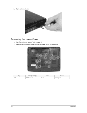
Step 1~6 Size (Quantity) M2.5 x L8 (6) Color Black Torque 3.0 kgf-cm 52 Chapter 3 Remove the four captive screws and the six screws (A) on page 50. 2. See "Removing the Battery Pack" on the lower cover. Pull it out from the slot. 2. Removing the Lower Cover 1.
Step 1~6 Size (Quantity) M2.5 x L8 (6) Color Black Torque 3.0 kgf-cm 52 Chapter 3 Remove the four captive screws and the six screws (A) on page 50. 2. See "Removing the Battery Pack" on the lower cover. Pull it out from the slot. 2. Removing the Lower Cover 1.

Aspire 5330/5730Z Service Guide
Page 63
Remove the lower cover from the lower case. Push out the latches on page 52.. 3. Removing the DIMM 1. See "Removing the Lower Cover" on both sides of the DIMM socket to carefully pry open the lower cover. 4. See "Removing the Battery Pack" on page 50. 2. Chapter 3 53 3. Use a plastic screw driver to release the DIMM.
Remove the lower cover from the lower case. Push out the latches on page 52.. 3. Removing the DIMM 1. See "Removing the Lower Cover" on both sides of the DIMM socket to carefully pry open the lower cover. 4. See "Removing the Battery Pack" on page 50. 2. Chapter 3 53 3. Use a plastic screw driver to release the DIMM.

Aspire 5330/5730Z Service Guide
Page 64
See "Removing the Lower Cover" on page 50. 2. Remove the white antenna cable that is taped to the WLAN board module. 54 Chapter 3 Remove the DIMM module. 4. Removing the WLAN Board Modules 1. See "Removing the Battery Pack" on page 52. 3.
See "Removing the Lower Cover" on page 50. 2. Remove the white antenna cable that is taped to the WLAN board module. 54 Chapter 3 Remove the DIMM module. 4. Removing the WLAN Board Modules 1. See "Removing the Battery Pack" on page 52. 3.

Aspire 5330/5730Z Service Guide
Page 66
See "Removing the Battery Pack" on page 52. 3. Remove the one screw (C) securing the hard disk drive module. Removing the Hard Disk Drive Module 1. 6. Detach the WLAN board from the WLAN socket. See "Removing the Lower Cover" on page 50. 2. NOTE: When attaching the antenna back to the WLAN board, make sure the cable are arranged properly. Step 1 Size (Quantity) M2 x L3 (1) Color Silver Torque 1.6 kgf-cm 56 Chapter 3
See "Removing the Battery Pack" on page 52. 3. Remove the one screw (C) securing the hard disk drive module. Removing the Hard Disk Drive Module 1. 6. Detach the WLAN board from the WLAN socket. See "Removing the Lower Cover" on page 50. 2. NOTE: When attaching the antenna back to the WLAN board, make sure the cable are arranged properly. Step 1 Size (Quantity) M2 x L3 (1) Color Silver Torque 1.6 kgf-cm 56 Chapter 3

Aspire 5330/5730Z Service Guide
Page 68
Step 1~2 Size (Quantity) M3 x L4 (2) Color Silver Removing the Optical Drive Module 1. Torque 3.0 kgf-cm 58 Chapter 3 See "Removing the Lower Cover" on page 50. 2. 7. See "Removing the Battery Pack" on page 52. Remove the two screws (D) securing the hard disk to the bracket and remove the hard disk from the bracket.
Step 1~2 Size (Quantity) M3 x L4 (2) Color Silver Removing the Optical Drive Module 1. Torque 3.0 kgf-cm 58 Chapter 3 See "Removing the Lower Cover" on page 50. 2. 7. See "Removing the Battery Pack" on page 52. Remove the two screws (D) securing the hard disk to the bracket and remove the hard disk from the bracket.

Aspire 5330/5730Z Service Guide
Page 72
Use a plastic screw driver to pry loose the side of the middle cover. 3. Removing the Middle Cover 1. See "Removing the Battery Pack" on page 50. 2. Carefully pry loose the middle cover from the latches securing it and remove the middle cover. 62 Chapter 3
Use a plastic screw driver to pry loose the side of the middle cover. 3. Removing the Middle Cover 1. See "Removing the Battery Pack" on page 50. 2. Carefully pry loose the middle cover from the latches securing it and remove the middle cover. 62 Chapter 3

Aspire 5330/5730Z Service Guide
Page 73
See "Removing the Battery Pack" on page 62. 3. Chapter 3 63 See "Removing the Middle Cover" on page 50. 2. Push down on the touchpad area. Carefully pry loose the keyboard and turn it over on the lock and release the latches securing the keyboard to the upper case. 4. Removing the Keyboard 1.
See "Removing the Battery Pack" on page 62. 3. Chapter 3 63 See "Removing the Middle Cover" on page 50. 2. Push down on the touchpad area. Carefully pry loose the keyboard and turn it over on the lock and release the latches securing the keyboard to the upper case. 4. Removing the Keyboard 1.

Aspire 5330/5730Z Service Guide
Page 74
See "Removing the Lower Cover" on page 50. 2. See "Removing the Battery Pack" on page 52. 3. Disconnect the heatsink fan connector from the main board to remove the keyboard. Removing the Heatsink Fan Module 1. Disconnect the keyboard cable from the main board. 64 Chapter 3 5.
See "Removing the Lower Cover" on page 50. 2. See "Removing the Battery Pack" on page 52. 3. Disconnect the heatsink fan connector from the main board to remove the keyboard. Removing the Heatsink Fan Module 1. Disconnect the keyboard cable from the main board. 64 Chapter 3 5.


