Aspire 5230 Service Guide
Page 7
...12 Lock Keys and embedded numeric keypad 12 Windows Keys 13 Hot Keys 14 Special Key 15 Using the System Utilities 16 Acer GridVista (dual-display compatible 16 Launch Manager 17 Hardware Specifications and Configurations 18 System Utilities 25 BIOS Setup Utility 25 Navigating ...General Information 46 Pre-disassembly Instructions 46 Disassembly Process 46 External Module Disassembly Process 47 External Modules Disassembly Flowchart 47 Removing the Battery Pack 48 Removing the SD dummy card 49 Removing the ExpressCard dummy card 50 Removing the Lower Covers 51 Removing the ...
...12 Lock Keys and embedded numeric keypad 12 Windows Keys 13 Hot Keys 14 Special Key 15 Using the System Utilities 16 Acer GridVista (dual-display compatible 16 Launch Manager 17 Hardware Specifications and Configurations 18 System Utilities 25 BIOS Setup Utility 25 Navigating ...General Information 46 Pre-disassembly Instructions 46 Disassembly Process 46 External Module Disassembly Process 47 External Modules Disassembly Flowchart 47 Removing the Battery Pack 48 Removing the SD dummy card 49 Removing the ExpressCard dummy card 50 Removing the Lower Covers 51 Removing the ...

Aspire 5230 Service Guide
Page 19
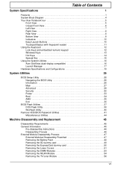
Houses the computer's main memory. Note: Do not cover or obstruct the opening of the fan. Houses the computer's hard disk (secured with screws). Chapter 1 9 Bottom View No. 1 2 3 4 5 6 7 Icon Item Battery bay Description Houses the computer's battery pack. Emits low frequency sound output. Enable the computer to stay cool, even after prolonged use. Locks the battery in position. Battery release latch Battery lock Memory compartment Sub-woofer Hard disk bay Ventilation slots and cooling fan Releases the battery for removal.
Houses the computer's main memory. Note: Do not cover or obstruct the opening of the fan. Houses the computer's hard disk (secured with screws). Chapter 1 9 Bottom View No. 1 2 3 4 5 6 7 Icon Item Battery bay Description Houses the computer's battery pack. Emits low frequency sound output. Enable the computer to stay cool, even after prolonged use. Locks the battery in position. Battery release latch Battery lock Memory compartment Sub-woofer Hard disk bay Ventilation slots and cooling fan Releases the battery for removal.
Aspire 5230 Service Guide
Page 20
... application (user-Programmable) Enables/disables the Bluetooth function. Icon Function Empowering Technology Acer Arcade Description Launch Acer Empowering Technology. (user-programmable) Launch Acer Arcade utility Wireless communication button/indicator Web browser Mail Bluetooth communication button/indicator Enables... : WLAN, Internet, email, Bluetooth, Arcade and Acer Empowering Technology. Charging: The light shows amber when the battery is activated. Battery HDD Num Lock Caps Lock Indicates the computer's battery status. Indicates the status of Bluetooth communication. 10 ...
... application (user-Programmable) Enables/disables the Bluetooth function. Icon Function Empowering Technology Acer Arcade Description Launch Acer Empowering Technology. (user-programmable) Launch Acer Arcade utility Wireless communication button/indicator Web browser Mail Bluetooth communication button/indicator Enables... : WLAN, Internet, email, Bluetooth, Arcade and Acer Empowering Technology. Charging: The light shows amber when the battery is activated. Battery HDD Num Lock Caps Lock Indicates the computer's battery status. Indicates the status of Bluetooth communication. 10 ...
Aspire 5230 Service Guide
Page 28
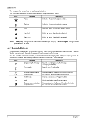
...Core logic Item CPU package Specification Mobile AMD Family 11h Processor • NB/SB AMD M780M/SB700 • ENE KB926 for Keyboard Controller, Battery management Unit, and RTC. • JMicron JMB385 for 5 in 1 controller • RS780M Has Integrated VGA solution • RealTek ALC268 for... = 100C; /recover 85C Item Specification BIOS vendor Phoenix BIOS Version V0.19T1 Features • Flash ROM 1MB • Support ISIPP • Support Acer UI • Support multi-boot • Suspend to RAM (S3) • Various hot-keys for system control • Support SMBIOS 2.3,PCI2.2. ...
...Core logic Item CPU package Specification Mobile AMD Family 11h Processor • NB/SB AMD M780M/SB700 • ENE KB926 for Keyboard Controller, Battery management Unit, and RTC. • JMicron JMB385 for 5 in 1 controller • RS780M Has Integrated VGA solution • RealTek ALC268 for... = 100C; /recover 85C Item Specification BIOS vendor Phoenix BIOS Version V0.19T1 Features • Flash ROM 1MB • Support ISIPP • Support Acer UI • Support multi-boot • Suspend to RAM (S3) • Various hot-keys for system control • Support SMBIOS 2.3,PCI2.2. ...
Aspire 5230 Service Guide
Page 34
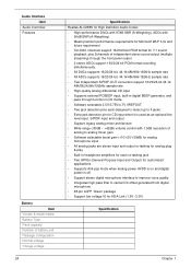
Audio Interface Item Audio Controller Features Battery Item Vendor & model name Battery Type Pack capacity Number of battery cell Package configuration Normal voltage Charge voltage 24 Specification Realtek ALC268S for High Definition Audio Codec • High-performance DACs with 97dB SNR (A-Weighting), ADCs ...
Audio Interface Item Audio Controller Features Battery Item Vendor & model name Battery Type Pack capacity Number of battery cell Package configuration Normal voltage Charge voltage 24 Specification Realtek ALC268S for High Definition Audio Codec • High-performance DACs with 97dB SNR (A-Weighting), ADCs ...

Aspire 5230 Service Guide
Page 36
... out or by hot key • HDD Local Stand-By mode by time out • LCD Local Stand-By mode by time out • Low battery alarm by beep • Auto-backlight off when LCD cover closed • Full ACPI 1.0B supported • LCD Auto-DIM mode by time out 26...
... out or by hot key • HDD Local Stand-By mode by time out • LCD Local Stand-By mode by time out • Low battery alarm by beep • Auto-backlight off when LCD cover closed • Full ACPI 1.0B supported • LCD Auto-DIM mode by time out 26...
Aspire 5230 Service Guide
Page 49
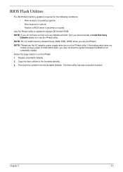
If the battery pack does not contain enough power to update the system BIOS flash ROM. Then boot the system from the bootable diskette. The flash utility has ...
If the battery pack does not contain enough power to update the system BIOS flash ROM. Then boot the system from the bootable diskette. The flash utility has ...
Aspire 5230 Service Guide
Page 58
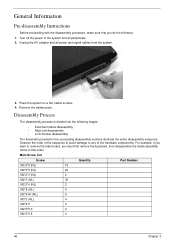
... off the power to any of the hardware components. Unplug the AC adapter and all peripherals. 2. Place the system on a flat, stable surface. 4. Remove the battery pack. Observe the order of the sequence to avoid damage to the system and all power and signal cables from the system. 3. General Information Pre...
... off the power to any of the hardware components. Unplug the AC adapter and all peripherals. 2. Place the system on a flat, stable surface. 4. Remove the battery pack. Observe the order of the sequence to avoid damage to the system and all power and signal cables from the system. 3. General Information Pre...

Aspire 5230 Service Guide
Page 60
Removing the Battery Pack 1. Slide and hold the battery release latch to the unlock position. 3. Turn computer over. 2. Slide the battery lock/unlock latch to the release position (1), then slide out the battery pack from the main unit (2). 2 1 48 Chapter 3
Removing the Battery Pack 1. Slide and hold the battery release latch to the unlock position. 3. Turn computer over. 2. Slide the battery lock/unlock latch to the release position (1), then slide out the battery pack from the main unit (2). 2 1 48 Chapter 3

Aspire 5230 Service Guide
Page 63
See "Removing the SD dummy card" on page 50. 4. See "Removing the ExpressCard dummy card" on page 49. 3. Quantity 1 2 1 Memory Cover HDD Cover Screw Type Chapter 3 51 Carefully open the memory cover. Removing the Lower Covers 1. WLAN Cover Step Memory Cover HDD Cover WLAN Cover Size M2.5*8 (NL) M2.5*8 (NL) M2.5*8 (NL) 5. See "Removing the Battery Pack" on page 48. 2. Remove the two screws from the memory and WLAN bays and loosen the two captive HDD bay screws.
See "Removing the SD dummy card" on page 50. 4. See "Removing the ExpressCard dummy card" on page 49. 3. Quantity 1 2 1 Memory Cover HDD Cover Screw Type Chapter 3 51 Carefully open the memory cover. Removing the Lower Covers 1. WLAN Cover Step Memory Cover HDD Cover WLAN Cover Size M2.5*8 (NL) M2.5*8 (NL) M2.5*8 (NL) 5. See "Removing the Battery Pack" on page 48. 2. Remove the two screws from the memory and WLAN bays and loosen the two captive HDD bay screws.

Aspire 5230 Service Guide
Page 65
Push out the release latches on page 51. 3. Remove the Memory Module cover See "Removing the Lower Covers" on both sides of the DIMM socket to release the DIMM module. 4. Repeat steps for the second DIMM module if present. Removing the DIMM Modules 1. See "Removing the Battery Pack" on page 48. 2. Chapter 3 53 Remove the DIMM module. 5. Remove the Battery Pack.
Push out the release latches on page 51. 3. Remove the Memory Module cover See "Removing the Lower Covers" on both sides of the DIMM socket to release the DIMM module. 4. Repeat steps for the second DIMM module if present. Removing the DIMM Modules 1. See "Removing the Battery Pack" on page 48. 2. Chapter 3 53 Remove the DIMM module. 5. Remove the Battery Pack.

Aspire 5230 Service Guide
Page 66
Disconnect the antenna cables from the WLAN board. 4. Remove the WLAN cover. See "Removing the Lower Covers" on page 48. 2. See "Removing the Battery Pack" on page 51. 3. Move the antenna cables away and remove the two screws on the WLAN board to release the WLAN board. Removing the WLAN Module 1. Step WLAN Module Size M2*3 (NL) Quantity 2 Screw Type 54 Chapter 3
Disconnect the antenna cables from the WLAN board. 4. Remove the WLAN cover. See "Removing the Lower Covers" on page 48. 2. See "Removing the Battery Pack" on page 51. 3. Move the antenna cables away and remove the two screws on the WLAN board to release the WLAN board. Removing the WLAN Module 1. Step WLAN Module Size M2*3 (NL) Quantity 2 Screw Type 54 Chapter 3

Aspire 5230 Service Guide
Page 70
Removing the Hard Disk Drive Module 1. Use the mylar tab to slide and lift up the hard disk drive module to device, avoid pressing down on it . 58 Chapter 3 NOTE: To prevent damage to remove. Remove the HDD cover, See "Removing the Lower Covers" on top of it or placing heavy objects on page 51. 3. See "Removing the Battery Pack" on page 48. 2.
Removing the Hard Disk Drive Module 1. Use the mylar tab to slide and lift up the hard disk drive module to device, avoid pressing down on it . 58 Chapter 3 NOTE: To prevent damage to remove. Remove the HDD cover, See "Removing the Lower Covers" on top of it or placing heavy objects on page 51. 3. See "Removing the Battery Pack" on page 48. 2.

Aspire 5230 Service Guide
Page 72
See "Removing the Battery Pack" on page 51. 3. See "Removing the Lower Covers" on page 48. 2. Grasp the front panel of the ODD and pull to remove from the main unit. 60 Chapter 3 Removing the Optical Drive Module 1. Remove the Memory cover. Step ODD Module Size M2.5*5(NL) Quantity 1 Screw Type 4. Remove the Battery Pack. Remove the screw securing the ODD module.
See "Removing the Battery Pack" on page 51. 3. See "Removing the Lower Covers" on page 48. 2. Grasp the front panel of the ODD and pull to remove from the main unit. 60 Chapter 3 Removing the Optical Drive Module 1. Remove the Memory cover. Step ODD Module Size M2.5*5(NL) Quantity 1 Screw Type 4. Remove the Battery Pack. Remove the screw securing the ODD module.
Aspire 5230 Service Guide
Page 76
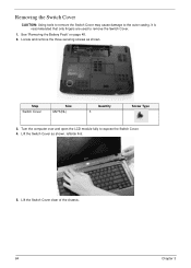
It is recommended that only fingers are used to expose the Switch Cover. 4. Lift the Switch Cover as shown. Step Switch Cover Size M2*3(NL) Quantity 3 Screw Type 3. Lift the Switch Cover clear of the chassis. 64 Chapter 3 See "Removing the Battery Pack" on page 48. 2. Turn the computer over and open the LCD module fully to remove the Switch Cover. 1. Locate and remove the three securing screws as shown, leftside first. 5. Removing the Switch Cover CAUTION: Using tools to remove the Switch Cover may cause damage to the outer casing.
It is recommended that only fingers are used to expose the Switch Cover. 4. Lift the Switch Cover as shown. Step Switch Cover Size M2*3(NL) Quantity 3 Screw Type 3. Lift the Switch Cover clear of the chassis. 64 Chapter 3 See "Removing the Battery Pack" on page 48. 2. Turn the computer over and open the LCD module fully to remove the Switch Cover. 1. Locate and remove the three securing screws as shown, leftside first. 5. Removing the Switch Cover CAUTION: Using tools to remove the Switch Cover may cause damage to the outer casing.

Aspire 5230 Service Guide
Page 77
Chapter 3 65 Push down on page 48.. 2. See "Removing the Battery Pack" on the two latches securing the keyboard to release the FFC. Turn the keyboard over and pull back the securing latch to the upper case. 3. Removing the Keyboard 1.
Chapter 3 65 Push down on page 48.. 2. See "Removing the Battery Pack" on the two latches securing the keyboard to release the FFC. Turn the keyboard over and pull back the securing latch to the upper case. 3. Removing the Keyboard 1.

Aspire 5230 Service Guide
Page 79
Using one hand, pull the cables completely through . Push the cables through the chassis, then turn over the computer and pull them completely through the battery housing. 4. Chapter 3 67 NOTE: Do not remove the adhesive tape. 5.
Using one hand, pull the cables completely through . Push the cables through the chassis, then turn over the computer and pull them completely through the battery housing. 4. Chapter 3 67 NOTE: Do not remove the adhesive tape. 5.
Aspire 5230 Service Guide
Page 102
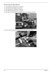
See "Removing the Battery Pack" on page 70. 5. See "Removing the Upper Cover" on page 48. 2. Disconnect the three cables from the top right of the mainboard as shown. 90 Chapter 3 Removing the Main Board 1. See "Removing the LCD Module" on page 65. 3. Disconnect the two cables from the bottom right of the mainboard as shown. 6. See "Removing the Keyboard" on page 68. 4.
See "Removing the Battery Pack" on page 70. 5. See "Removing the Upper Cover" on page 48. 2. Disconnect the three cables from the top right of the mainboard as shown. 90 Chapter 3 Removing the Main Board 1. See "Removing the LCD Module" on page 65. 3. Disconnect the two cables from the bottom right of the mainboard as shown. 6. See "Removing the Keyboard" on page 68. 4.
Aspire 5230 Service Guide
Page 105
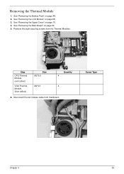
Remove the eight securing screws from mainboard. Step CPU Thermal Module (red callout) VGA Thermal Module (blue callout) Size M2*6.5 M2*L3 Quantity 4 4 6. Screw Type Chapter 3 93 See "Removing the LCD Module" on page 90. 5. See "Removing the Main Board" on page 68. 3. See "Removing the Battery Pack" on page 70. 4. See "Removing the Upper Cover" on page 48. 2. Disconnect the fan module cable from the Thermal Modules. Removing the Thermal Module 1.
Remove the eight securing screws from mainboard. Step CPU Thermal Module (red callout) VGA Thermal Module (blue callout) Size M2*6.5 M2*L3 Quantity 4 4 6. Screw Type Chapter 3 93 See "Removing the LCD Module" on page 90. 5. See "Removing the Main Board" on page 68. 3. See "Removing the Battery Pack" on page 70. 4. See "Removing the Upper Cover" on page 48. 2. Disconnect the fan module cable from the Thermal Modules. Removing the Thermal Module 1.
Aspire 5230 Service Guide
Page 107
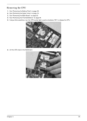
See "Removing the Upper Cover" on page 90. 4. See "Removing the Main Board" on page 70. 3. Chapter 3 95 See "Removing the Thermal Module" on page 48. 2. See "Removing the Battery Pack" on page 93. 5. Using a flat screwdriver, turn the CPU socket latch counter-clockwise 180° to release the CPU. 6. Lift the CPU clear of the Mainboard. Removing the CPU 1.
See "Removing the Upper Cover" on page 90. 4. See "Removing the Main Board" on page 70. 3. Chapter 3 95 See "Removing the Thermal Module" on page 48. 2. See "Removing the Battery Pack" on page 93. 5. Using a flat screwdriver, turn the CPU socket latch counter-clockwise 180° to release the CPU. 6. Lift the CPU clear of the Mainboard. Removing the CPU 1.


