
Acer Aspire 4540 Series Service Guide
Page 52
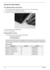
Observe the order of the hardware components. Remove the battery pack. Main Screw List Description Quantity Acer P/N M1.98D 3.0L K 4.6D 0.8T ZK 21 86.PAA02.001 M2.46D 3.0L K 5.5D 0.8T ZK 11 86.PAA02.002 M2.5D 5L K 5.5D ZK ... you want to any of the sequence to avoid damage to remove the main board, you must first remove the keyboard, then disassemble the inside assembly frame in the succeeding disassembly sections illustrate the entire disassembly sequence. Unplug the AC adapter and all peripherals. 2. General Information Pre-disassembly Instructions Before proceeding...
Observe the order of the hardware components. Remove the battery pack. Main Screw List Description Quantity Acer P/N M1.98D 3.0L K 4.6D 0.8T ZK 21 86.PAA02.001 M2.46D 3.0L K 5.5D 0.8T ZK 11 86.PAA02.002 M2.5D 5L K 5.5D ZK ... you want to any of the sequence to avoid damage to remove the main board, you must first remove the keyboard, then disassemble the inside assembly frame in the succeeding disassembly sections illustrate the entire disassembly sequence. Unplug the AC adapter and all peripherals. 2. General Information Pre-disassembly Instructions Before proceeding...
Acer Aspire 4540 Series Service Guide
Page 53
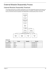
... to remove the main board, you want to be removed during servicing. For example, if you must first remove the keyboard, then disassemble the inside assembly frame in that order.
... to remove the main board, you want to be removed during servicing. For example, if you must first remove the keyboard, then disassemble the inside assembly frame in that order.
Acer Aspire 4540 Series Service Guide
Page 103
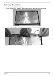
Remove the antenna cables and assembly from obstructions. 3. Removing the Antennas 1. Remove the tab securing the left and right antennas to the LCD module and lift the antennas clear. 4. Remove the strips holding the antenna cables in place. Chapter 3 93 Ensure the cables are free from the LCD module. See "Removing the LCD Panel" on page 90. 2.
Remove the antenna cables and assembly from obstructions. 3. Removing the Antennas 1. Remove the tab securing the left and right antennas to the LCD module and lift the antennas clear. 4. Remove the strips holding the antenna cables in place. Chapter 3 93 Ensure the cables are free from the LCD module. See "Removing the LCD Panel" on page 90. 2.

Acer Aspire 4540 Series Service Guide
Page 138
Align the Hinge Covers screw hole side up and slide them on the inside. Ensure that the correct cover is used during reassembly. 1. Replace the two securing screws and caps. Replacing the Hinge Covers IMPORTANT: The left and right Hinge Covers are shaped differently and marked L and R on to the hinge assemblies. 2. Step Hinge Covers Size M2*3 Quantity 2 Screw Type 128 Chapter 3
Align the Hinge Covers screw hole side up and slide them on the inside. Ensure that the correct cover is used during reassembly. 1. Replace the two securing screws and caps. Replacing the Hinge Covers IMPORTANT: The left and right Hinge Covers are shaped differently and marked L and R on to the hinge assemblies. 2. Step Hinge Covers Size M2*3 Quantity 2 Screw Type 128 Chapter 3
Acer Aspire 4540 Series Service Guide
Page 164
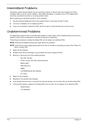
...test for damage. FRU replacement should be caused by the computer. Do not replace a non-defective FRU: • System board • LCD assembly 154 Chapter 4 If any problems are supported by a variety of the failure is detected, do not isolate non-defective FRU). Visually check them ...the system board in loop mode at a time until you find the failing FRU. 7. If the problem remains, replace the following devices: • Non-Acer devices • Printer, mouse, and other external devices • Battery pack • Hard disk drive • DIMM • CD-ROM/Diskette drive ...
...test for damage. FRU replacement should be caused by the computer. Do not replace a non-defective FRU: • System board • LCD assembly 154 Chapter 4 If any problems are supported by a variety of the failure is detected, do not isolate non-defective FRU). Visually check them ...the system board in loop mode at a time until you find the failing FRU. 7. If the problem remains, replace the following devices: • Non-Acer devices • Printer, mouse, and other external devices • Battery pack • Hard disk drive • DIMM • CD-ROM/Diskette drive ...
Acer Aspire 4540 Series Service Guide
Page 181
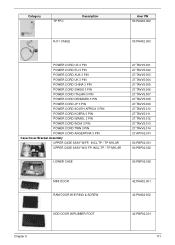
Category TP FFC Description RJ11 CABLE Acer PN 50.PAA02.002 50.PAA02.003 POWER CORD US 3 PIN POWER CORD EU 3 PIN POWER CORD AUS 3 PIN POWER CORD UK 3 PIN POWER CORD ... AFRICA 3 PIN POWER CORD KOERA 3 PIN POWER CORD ISRAEL 3 PIN POWER CORD INDIA 3 PIN POWER CORD TWN 3 PIN POWER CORD ARGENTINA 3 PIN Case/Cover/Bracket Assembly UPPER CASE ASSY W/FP, INCL.TP / TP MYLAR UPPER CASE ASSY W/O FP, INCL.TP / TP MYLAR 27.TAVV5.001 27.TAVV5.002 27.TAVV5.003...
Category TP FFC Description RJ11 CABLE Acer PN 50.PAA02.002 50.PAA02.003 POWER CORD US 3 PIN POWER CORD EU 3 PIN POWER CORD AUS 3 PIN POWER CORD UK 3 PIN POWER CORD ... AFRICA 3 PIN POWER CORD KOERA 3 PIN POWER CORD ISRAEL 3 PIN POWER CORD INDIA 3 PIN POWER CORD TWN 3 PIN POWER CORD ARGENTINA 3 PIN Case/Cover/Bracket Assembly UPPER CASE ASSY W/FP, INCL.TP / TP MYLAR UPPER CASE ASSY W/O FP, INCL.TP / TP MYLAR 27.TAVV5.001 27.TAVV5.002 27.TAVV5.003...

