Aspire 3000 / 3500 / 5000 Service Guide
Page 38
AC Adapter Item Regulatory Requirements Specification Safety Requirements: 1.The subject product ... 336/EEC. 3.The subject product rated 100-120V must comply with low voltage directive 73/23EEC. Power Management Power Saving Mode Standby Mode Enter Standby Mode when 1.Standby/Hibernation hot-key is pressed and system is not...must meet the EMI requirements of time. Phenomenon T The buzzer beeps T The Sleep indicator lights up T All power shuts off T The display shuts off ) Environmental Requirements Item Temperature Operating Non-operating Package storage Humidity Operating Non-...
AC Adapter Item Regulatory Requirements Specification Safety Requirements: 1.The subject product ... 336/EEC. 3.The subject product rated 100-120V must comply with low voltage directive 73/23EEC. Power Management Power Saving Mode Standby Mode Enter Standby Mode when 1.Standby/Hibernation hot-key is pressed and system is not...must meet the EMI requirements of time. Phenomenon T The buzzer beeps T The Sleep indicator lights up T All power shuts off T The display shuts off ) Environmental Requirements Item Temperature Operating Non-operating Package storage Humidity Operating Non-...

Aspire 3000 / 3500 / 5000 Service Guide
Page 56
Unplug the AC adapter and all peripherals. 2. NOTE: Aspire 9100 series product uses mylar or tape to fasten the FFC/FPC/connectors/cable, you may need to the system and all power and signal cables from the system . Turn off the power to tear the tape or mylar before you do the following: 1. General Information Before You Begin Before proceeding with the disassembly procedure, make sure that you disconnect different FFC/FPC/connectors. 47 Chapter 3
Unplug the AC adapter and all peripherals. 2. NOTE: Aspire 9100 series product uses mylar or tape to fasten the FFC/FPC/connectors/cable, you may need to the system and all power and signal cables from the system . Turn off the power to tear the tape or mylar before you do the following: 1. General Information Before You Begin Before proceeding with the disassembly procedure, make sure that you disconnect different FFC/FPC/connectors. 47 Chapter 3

Aspire 3000 / 3500 / 5000 Service Guide
Page 77
...repeat the failing operation. Remove the battery pack. 2. Connect the power adapter and check that the DIMM is fully installed into the connector. Follow the instructions in the following power sources: 1. NOTE: Make sure that power is supplied by the battery pack. If any of the following ...list: T "Check the Power Adapter" on page 69 T "Check the Battery Pack" on the screen, or...
...repeat the failing operation. Remove the battery pack. 2. Connect the power adapter and check that the DIMM is fully installed into the connector. Follow the instructions in the following power sources: 1. NOTE: Make sure that power is supplied by the battery pack. If any of the following ...list: T "Check the Power Adapter" on page 69 T "Check the Battery Pack" on the screen, or...
Aspire 3000 / 3500 / 5000 Service Guide
Page 78
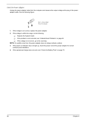
... Pin 2: 0V, Ground 1. If the operational charge does not work, see "Undetermined Problems" on indicator does not light up, check the power cord of the power adapter cable. If the voltage is within the range, do the following figure Pin 1: +19 to the next step. If the voltage is not... correct, replace the power adapter. 2. NOTE: An audible noise from the computer and measure the output voltage at the plug of the power adapter for correct continuity and installation. 4. T If the voltage is not corrected, see "Check the...
... Pin 2: 0V, Ground 1. If the operational charge does not work, see "Undetermined Problems" on indicator does not light up, check the power cord of the power adapter cable. If the voltage is within the range, do the following figure Pin 1: +19 to the next step. If the voltage is not... correct, replace the power adapter. 2. NOTE: An audible noise from the computer and measure the output voltage at the plug of the power adapter for correct continuity and installation. 4. T If the voltage is not corrected, see "Check the...
Aspire 3000 / 3500 / 5000 Service Guide
Page 79
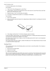
...1. Remove the battery pack and measure the voltage between battery terminals 1(+) and 6(ground). If the voltage is on the screen for both battery and adapter. 4. If the charge indicator still does not light up , replace the battery pack. Touchpad Check If the touchpad doesn't work, do the following ... the touchpad, the pointer drifts on recharging or discharging. After you identify first the problem is still less than 50% of time. In Power Meter, confirm that has less than 7.5 Vdc after recharging, replace the battery. If the battery status indicator does not light up, remove ...
...1. Remove the battery pack and measure the voltage between battery terminals 1(+) and 6(ground). If the voltage is on the screen for both battery and adapter. 4. If the charge indicator still does not light up , replace the battery pack. Touchpad Check If the touchpad doesn't work, do the following ... the touchpad, the pointer drifts on recharging or discharging. After you identify first the problem is still less than 50% of time. In Power Meter, confirm that has less than 7.5 Vdc after recharging, replace the battery. If the battery status indicator does not light up, remove ...
Aspire 3000 / 3500 / 5000 Service Guide
Page 83
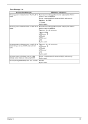
... Hard disk drive LCD inverter ID LCD cable LCD Inverter LCD System board No beep, power-on indicator turns on an external CRT. Reconnect the LCD connectors. Power source (battery pack and power adapter). But you can see POST on and LCD is blank. LCD inverter ID LCD cable..." on LCD during POST but system runs correctly. LED board. See "Power System Check" on and LCD is blank. Power source (battery pack and power adapter). System board No beep during POST. System board. No beep, power-on indicator turns on page 68. Error Message List No beep Error Messages...
... Hard disk drive LCD inverter ID LCD cable LCD Inverter LCD System board No beep, power-on indicator turns on an external CRT. Reconnect the LCD connectors. Power source (battery pack and power adapter). But you can see POST on and LCD is blank. LCD inverter ID LCD cable..." on LCD during POST but system runs correctly. LED board. See "Power System Check" on and LCD is blank. Power source (battery pack and power adapter). System board No beep during POST. System board. No beep, power-on indicator turns on page 68. Error Message List No beep Error Messages...

Aspire 3000 / 3500 / 5000 Service Guide
Page 88
... Sequence Indicator incorrectly remains off . See "Power System Check" on . Hold and press the power switch for more than 4 seconds. Battery pack Power adapter Hard drive & battery connection board System board Power source (battery pack and power adapter). Battery pack Power adapter Hard drive & battery connection board System board Power source (battery pack and power adapter). Index of Symptom-to execute "Load...
... Sequence Indicator incorrectly remains off . See "Power System Check" on . Hold and press the power switch for more than 4 seconds. Battery pack Power adapter Hard drive & battery connection board System board Power source (battery pack and power adapter). Battery pack Power adapter Hard drive & battery connection board System board Power source (battery pack and power adapter). Index of Symptom-to execute "Load...

Aspire 3000 / 3500 / 5000 Service Guide
Page 92
...check them for damage. Do not replace a non-defective FRU: T System board T LCD assembly 83 Chapter 4 Power-on page 68): 1. If the problem remains, replace the following devices: T Non-Acer devices T Printer, mouse, and other external devices T Battery pack T Hard disk drive T DIMM T CD-ROM... computer. Undetermined Problems The diagnostic problems does not identify which adapter or device failed, which installed devices are incorrect, whether a short circuit is suspected, or whether the system is operating correctly. (See "Power System Check" on the computer. 5. NOTE: Verify that ...
...check them for damage. Do not replace a non-defective FRU: T System board T LCD assembly 83 Chapter 4 Power-on page 68): 1. If the problem remains, replace the following devices: T Non-Acer devices T Printer, mouse, and other external devices T Battery pack T Hard disk drive T DIMM T CD-ROM... computer. Undetermined Problems The diagnostic problems does not identify which adapter or device failed, which installed devices are incorrect, whether a short circuit is suspected, or whether the system is operating correctly. (See "Power System Check" on the computer. 5. NOTE: Verify that ...

Aspire 3000 / 3500 / 5000 Service Guide
Page 115
...Xircom Credit Card Modem 56 IBM 56K Double Jack Modem US Robotics Megahertz 128K ISDN Card 405R17T7117M IBM OBI International ISDN PC Card Acer 211c 21" Viewsonic PF790 19" Acer FP751 17" TFT LCD IBM Color TFT LCD 14" Compaq Color Monitor NET Color Monitor 20" Mozo 17" TFT LCD (DVI... 740 Parallel Interface HP DeskJet 890C HP DeskJet 880C Parallel Interface HP LaserJet 6MP HP LaserJet 2200 Appendix B 106 Projector I /O - ODD Item AC Adapter (3 pin) Power Cord Battery Li-Ion, 8 cells Network Adapters LAN Ethernet/10baseT/100base Multifunction Card (Combo) LAN Token Ring Wireless LAN Card Modem...
...Xircom Credit Card Modem 56 IBM 56K Double Jack Modem US Robotics Megahertz 128K ISDN Card 405R17T7117M IBM OBI International ISDN PC Card Acer 211c 21" Viewsonic PF790 19" Acer FP751 17" TFT LCD IBM Color TFT LCD 14" Compaq Color Monitor NET Color Monitor 20" Mozo 17" TFT LCD (DVI... 740 Parallel Interface HP DeskJet 890C HP DeskJet 880C Parallel Interface HP LaserJet 6MP HP LaserJet 2200 Appendix B 106 Projector I /O - ODD Item AC Adapter (3 pin) Power Cord Battery Li-Ion, 8 cells Network Adapters LAN Ethernet/10baseT/100base Multifunction Card (Combo) LAN Token Ring Wireless LAN Card Modem...

Aspire 3000 / 3500 / 5000 Service Guide
Page 122
... 16 num lock on indicator 12 O Online Support Information 110 P Panel Bottom 11 right 10 PC Card 12, 26 PCMCIA 26 Power Management 29 Power System Check 68 Battery Pack 70 Power Adapter 69 R Removing the Battery Pack 50 S Second Level Cache 20 speakers hotkey 16 Standby Mode 29 System Check Procedures 67 System...
... 16 num lock on indicator 12 O Online Support Information 110 P Panel Bottom 11 right 10 PC Card 12, 26 PCMCIA 26 Power Management 29 Power System Check 68 Battery Pack 70 Power Adapter 69 R Removing the Battery Pack 50 S Second Level Cache 20 speakers hotkey 16 Standby Mode 29 System Check Procedures 67 System...


