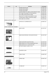
Acer Aspire 1710 Service Guide
Page 7
... thermal module 52 Remove CPU 52 Remove the memory 52 Remove VGA card 52 Detach the wireless card 53 Remove moden card 53 Remove the inverter cover 53 Detach the upper system cover 54 Remove the LCD module 54 Remove the LCD panel 55 Remove the...
Acer Aspire 1710 Service Guide
Page 37
...-ION 6600mAH 3.8V 12 4S3P 14.4V Specification DC-AC LCD Inverter Item Vendor & model name Input voltage (V) Input current (mA) Output voltage Output voltage frequency (kHz) Output Current Ambit 10 ~ 20V 1A (max.) 725Vrms 40 ~ 65Hz 1.5 mArms ~ 3.75mArms Specification 28 Aspire 1710 key Yes Yes Battery Item Vendor & model name Battery Type...
Acer Aspire 1710 Service Guide
Page 57
... cable and IDE coaxial cable Rx4 x4 CPU Upper System Cover (Middle Cover) Cx3 Inverter Cover Jx4 Hinge Cover x6 Keyboard HDD Bracket HDD LED Cable LCD Outer Shield (LCD panel) Remove inverter board mylar Inverter Board x2 Brackets Inverter Board Dx8 LCD Bx2 x4 on the components that order. For example, if you...
Acer Aspire 1710 Service Guide
Page 62
Remove the screws on the MDC (modem card) 2. Detach the card from the modem cable. 3. Remove the screws as shown here. 2. Remove the inverter cover. 53 Aspire 1710 Disconnect the two wireless cables. Release the cable Remove the inverter cover 1. Remove moden card 1. Detach the wireless card. 2. Detach the wireless card 1.
Acer Aspire 1710 Service Guide
Page 64
Remove the LCD panel 1. Remove the LCD panel. Detach the LCD skirting board (LCD bezel) by following the instruction here. 4. Remove the inverter board 1. Detach the silicon line pad by following the instruction here. Unscrew the three screws on the edge of the LCD panel on the side mount. 5. Remove the tape and disconnect the inverter cable. 55 Aspire 1710 Remove the TEN screws on both sides. 3. And the other side. 2.
Acer Aspire 1710 Service Guide
Page 65
Chapter 3 56 Remove the mylar that secure the inverter board bracket. Remove the two screws that covering the inverter board. 5. Disconnect the inverter power cable from the inverter board. 4. Follow the same procedure on the other inverter cable. 3. 2.
Acer Aspire 1710 Service Guide
Page 85
...correctly. See "Power System Check" on page 70. But you can see POST on indicator turns off and LCD is blank. LCD inverter ID LCD cable LCD inverter LCD System board No beep, power-on indicator turns on and a blinking cursor shown on and LCD is connected tightly and correctly.... during POST. Reconnect the LCD connectors. LED board. Ensure every connector is blank. Reconnect the LCD connector Hard disk drive LCD inverter ID LCD cable LCD Inverter LCD System board No beep, power-on indicator turns on LCD during POST but system runs correctly. Error Message List No beep ...
Acer Aspire 1710 Service Guide
Page 86
...inverter board runs correctly Inverter board System board Power-Related Symptoms Symptom / Error Power shuts down during operation The system doesn't power-on. See "Power System Check" on page 72. System board See "Check the Battery Pack" on page 70. See "Power System Check" on page 70. Battery pack System board 77 Aspire 1710...switch for more than 4 seconds. LCD inverter ID LCD cable LCD inverter LCD System board Reconnect the LCD connector LCD inverter ID LCD cable LCD inverter LCD System board LCD inverter ID LCD inverter LCD cable LCD System board Indicator-Related Symptoms...
Acer Aspire 1710 Service Guide
Page 100
... W/ 6 IN 1 SKU W/O BLUETOOTH SKU BASE CASE W/ 6 IN 1 BLUETOOTH SKU BETTERY DOMMY COVER W/ FOOT 60.A15V7.003 60.A15V7.004 60.A15V7.005 42.A08V7.001 INVERTER COVER HINGH COVER UPPER CASE 42.A08V7.002 42.A08V7.003 60.A08V7.003 I/O BRACKET 91 33.A08V7.001 Aspire 1710
Acer Aspire 1710 Service Guide
Page 117
... Chipsets 22 contrast hotkeys 18 Controllers 22 Core logic 22 CPU core voltage 22 I/O voltage 22 package 22 type 22 D Index Index DC-AC LCD Inverter 28 DIMM Combinations 23 Disassembly CD-ROM/DVD-ROM Module 51 Machine 46 Procedure Flowchart 48 Display 1 display hotkeys 18 Display Standby Mode 30 DVD...