
User Manual
Page 4
...! Use conditions This part complies with FCC regulations. The CD-ROM drive's classification label (shown below) is likely to result in this server. CLASS 1 LASER PRODUCT CAUTION: INVISIBLE LASER RADIATION WHEN OPEN. Operation is granted by the manufacturer could void the user's authority, which is...Canadian Interference-Causing Equipment Regulations. Changes or modifications not expressly approved by the Federal Communications Commission, to operate this server is a laser product. Laser compliance statement The CD-ROM drive in interference to radio and TV reception.
...! Use conditions This part complies with FCC regulations. The CD-ROM drive's classification label (shown below) is likely to result in this server. CLASS 1 LASER PRODUCT CAUTION: INVISIBLE LASER RADIATION WHEN OPEN. Operation is granted by the manufacturer could void the user's authority, which is...Canadian Interference-Causing Equipment Regulations. Changes or modifications not expressly approved by the Federal Communications Commission, to operate this server is a laser product. Laser compliance statement The CD-ROM drive in interference to radio and TV reception.

User Manual
Page 8
Contents ESD precautions 29 Preinstallation instructions 30 Post-installation instructions 30 Opening the server 31 Before opening the server 31 To remove the side panel 32 To remove the front panel 33 Installing and removing storage devices 34 To install a 5.25-inch storage device ...
Contents ESD precautions 29 Preinstallation instructions 30 Post-installation instructions 30 Opening the server 31 Before opening the server 31 To remove the side panel 32 To remove the front panel 33 Installing and removing storage devices 34 To install a 5.25-inch storage device ...

User Manual
Page 9
... activity light does not light 88 CD-ROM drive or DVD-ROM drive activity light does not light 88 Cannot connect to a server 88 Problems with the network 89 The server hangs when the drivers are loaded. 89 Diagnostics pass but the connection fails. 89 The controller stopped working when an add...
... activity light does not light 88 CD-ROM drive or DVD-ROM drive activity light does not light 88 Cannot connect to a server 88 Problems with the network 89 The server hangs when the drivers are loaded. 89 Diagnostics pass but the connection fails. 89 The controller stopped working when an add...
User Manual
Page 10
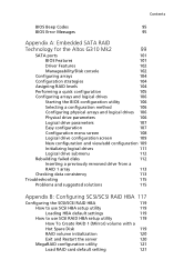
Contents BIOS Beep Codes 95 BIOS Error Messages 95 Appendix A: Embedded SATA RAID Technology for the Altos G310 Mk2 99 SATA ports 101 BIOS Features 101 Driver Features 102 Manageability/Disk console 102 Configuring arrays 104 Configuration strategies 104 Assigning RAID levels 104 Performing a ... SCSI RAID HBA setup utility 119 How To Create RAID 1 (Mirror) volume with a Hot Spare Disk 119 RAID volume initialization 120 Exit and Restart the server 120 MegaRAID configuration utility 121 Load RAID card default setting 121
Contents BIOS Beep Codes 95 BIOS Error Messages 95 Appendix A: Embedded SATA RAID Technology for the Altos G310 Mk2 99 SATA ports 101 BIOS Features 101 Driver Features 102 Manageability/Disk console 102 Configuring arrays 104 Configuration strategies 104 Assigning RAID levels 104 Performing a ... SCSI RAID HBA setup utility 119 How To Create RAID 1 (Mirror) volume with a Hot Spare Disk 119 RAID volume initialization 120 Exit and Restart the server 120 MegaRAID configuration utility 121 Load RAID card default setting 121
User Manual
Page 14
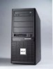
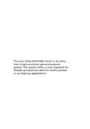
The Acer Altos G310 Mk2 server is an entry level single-processor general purpose system. The system offers a new standard for flexible productivity ideal for small business or workgroup applications.
The Acer Altos G310 Mk2 server is an entry level single-processor general purpose system. The system offers a new standard for flexible productivity ideal for small business or workgroup applications.

User Manual
Page 15
...8226; Maximum upgrade - 4 GB • Two-way interleaving support Warning! Processor • Support for an Intel Pentium 4 processor in the Altos G310 Mk2. When using multiple memory modules it is recommended that you AVOID using modules from different manufacturers or that run at different speeds from each other... the configuration of identical type, banking and stacking technology, and vendor should be encountered if mixed memory types are installed on the same server board. CPU Pentium 4 Celeron D FSB (MHz) 800 800 533 533 Memory Type DDR2 400 DDR2 533 DDR2 400 DDR2 533 Memory...
...8226; Maximum upgrade - 4 GB • Two-way interleaving support Warning! Processor • Support for an Intel Pentium 4 processor in the Altos G310 Mk2. When using multiple memory modules it is recommended that you AVOID using modules from different manufacturers or that run at different speeds from each other... the configuration of identical type, banking and stacking technology, and vendor should be encountered if mixed memory types are installed on the same server board. CPU Pentium 4 Celeron D FSB (MHz) 800 800 533 533 Memory Type DDR2 400 DDR2 533 DDR2 400 DDR2 533 Memory...

User Manual
Page 17
... (optional) for efficient system setup and installation. • Acer Server Manager (ASM) suite of Acer's mission, as a company that cares about its end users, is no exception to provide features that make operation, maintenance, and upgrading your system simpler and faster. The Altos G310 Mk2 is to this rule. 5 Caring features Part of comprehensive management tools...
... (optional) for efficient system setup and installation. • Acer Server Manager (ASM) suite of Acer's mission, as a company that cares about its end users, is no exception to provide features that make operation, maintenance, and upgrading your system simpler and faster. The Altos G310 Mk2 is to this rule. 5 Caring features Part of comprehensive management tools...

User Manual
Page 20
8 • Operating Systems supported • Microsoft® Windows® Server 2003 • Red Hat® Enterprise Linux 3.0 • Novell Netware 6.5 1 System information
8 • Operating Systems supported • Microsoft® Windows® Server 2003 • Red Hat® Enterprise Linux 3.0 • Novell Netware 6.5 1 System information

User Manual
Page 37
25 Turning off the system To turn off the server, on the Windows task bar click on the Start button, point to assist you are disconnected from the dropdown window then click...8226; The external power cable may be loosely connected. Power-on problems If the system does not boot after you are unable to shutdown the server within Windows, press and hold the power button for at least four seconds to boot, ask your power outlet. • Loose or improperly... to the power source and to perform this task. If you . You can then turn off all peripherals connected to your server.
25 Turning off the system To turn off the server, on the Windows task bar click on the Start button, point to assist you are disconnected from the dropdown window then click...8226; The external power cable may be loosely connected. Power-on problems If the system does not boot after you are unable to shutdown the server within Windows, press and hold the power button for at least four seconds to boot, ask your power outlet. • Loose or improperly... to the power source and to perform this task. If you . You can then turn off all peripherals connected to your server.

User Manual
Page 41
...protective packaging until you install any procedure requiring ESD protection. These sections contain important ESD precautions along with the server throughout any server component, we do not recommend that you perform these components, contact your dealer or a qualified service technician... for assistance. Important: Observe the installation precautions described in the subsequent section when installing or removing a server component. Installation precautions Before you are upgradeable such as the drives, the CPU, the memory, and the expansion cards...
...protective packaging until you install any procedure requiring ESD protection. These sections contain important ESD precautions along with the server throughout any server component, we do not recommend that you perform these components, contact your dealer or a qualified service technician... for assistance. Important: Observe the installation precautions described in the subsequent section when installing or removing a server component. Installation precautions Before you are upgradeable such as the drives, the CPU, the memory, and the expansion cards...
User Manual
Page 42
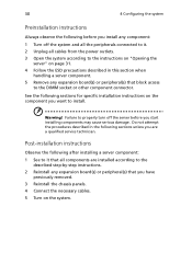
...block access to the DIMM socket or other component connector. Do not attempt the procedures described in this section when handling a server component. 5 Remove any expansion board(s) or peripheral(s) that you are installed according to the described step-by-step instructions. .... 5 Turn on the component you start installing components may cause serious damage. Post-installation instructions Observe the following after installing a server component: 1 See to it . 2 Unplug all components are a qualified service technician. 30 4 Configuring the system Preinstallation instructions Always...
...block access to the DIMM socket or other component connector. Do not attempt the procedures described in this section when handling a server component. 5 Remove any expansion board(s) or peripheral(s) that you are installed according to the described step-by-step instructions. .... 5 Turn on the component you start installing components may cause serious damage. Post-installation instructions Observe the following after installing a server component: 1 See to it . 2 Unplug all components are a qualified service technician. 30 4 Configuring the system Preinstallation instructions Always...

User Manual
Page 43
... front and left side panels are removable to allow access to open the server before you have turned off the system and all the peripherals connected to it. 2 Unplug all peripherals connected to it. Note: Because of the G310 Mk2 design specification, only the side panel needs to be removed to the following...
... front and left side panels are removable to allow access to open the server before you have turned off the system and all the peripherals connected to it. 2 Unplug all peripherals connected to it. Note: Because of the G310 Mk2 design specification, only the side panel needs to be removed to the following...

User Manual
Page 44
To remove the side panel: 1 Locate the System Keys (if necessary) and unlock the system lock on the front panel. 2 Loosen the thumbscrews located at the rear end of the left panel (1). 3 Slide the left panel rearward (2) before detaching it from the chassis. 32 4 Configuring the system To remove the side panel The side panel is attached to the server by two (non-removable) thumbscrews.
To remove the side panel: 1 Locate the System Keys (if necessary) and unlock the system lock on the front panel. 2 Loosen the thumbscrews located at the rear end of the left panel (1). 3 Slide the left panel rearward (2) before detaching it from the chassis. 32 4 Configuring the system To remove the side panel The side panel is attached to the server by two (non-removable) thumbscrews.

User Manual
Page 48
... ESD precautions on page 29. 1 Open the socket lever by doing the following: (1) Touch the metal chassis before touching the processor or server board. Reduce the risk of your server. the standby power LED should not be appropriate. Keep part of electrostatic discharge (ESD) damage to the processor by pushing the lever...
... ESD precautions on page 29. 1 Open the socket lever by doing the following: (1) Touch the metal chassis before touching the processor or server board. Reduce the risk of your server. the standby power LED should not be appropriate. Keep part of electrostatic discharge (ESD) damage to the processor by pushing the lever...

User Manual
Page 51
39 To install the processor fan heat sink The Altos G310 Mk2's server board has an integrated processor fan heat sink retention mechanism (RM). Connecting the processor fan heat sink cable Connect the processor fan heat sink cable to the 4-pin processor fan header.
39 To install the processor fan heat sink The Altos G310 Mk2's server board has an integrated processor fan heat sink retention mechanism (RM). Connecting the processor fan heat sink cable Connect the processor fan heat sink cable to the 4-pin processor fan header.

User Manual
Page 52
... a Processor 1 Observe the safety and ESD precautions at the beginning of the heat sink. 7 Twist the heat sink slightly to the server. If installing a replacement processor, see "To install the Processor" on the corners of this section. 2 Turn off the... server. 3 Remove the AC power cord from the server. 4 Remove the server's cover. See the documentation that accompanied your server chassis for instructions on removing the server's cover. 5 Unplug the processor fan cable from the server board. 6 Loosen the four captive screws on page 36...
... a Processor 1 Observe the safety and ESD precautions at the beginning of the heat sink. 7 Twist the heat sink slightly to the server. If installing a replacement processor, see "To install the Processor" on the corners of this section. 2 Turn off the... server. 3 Remove the AC power cord from the server. 4 Remove the server's cover. See the documentation that accompanied your server chassis for instructions on removing the server's cover. 5 Unplug the processor fan cable from the server board. 6 Loosen the four captive screws on page 36...

User Manual
Page 53
41 Upgrading the system memory Memory configuration This section includes instructions for removing and installing a memory module. Memory Channel A DIMM0 512 MB 1 GB 512 MB 1 GB 512 MB 1 GB DIMM1 512 MB 1 GB Memory Channel B DIMM0 DIMM1 512 MB 1 GB 512 MB 1 GB 512 MB 1 GB Memory Interleave 1-way 2-way 2-way The memory modules are located on the main server board as shown below: Channel A DIMM 0 DIMM 1 Channel B DIMM 0 DIMM 1 The two tables (below) summarize the characteristics of 1-way and 2way memory interleave configurations.
41 Upgrading the system memory Memory configuration This section includes instructions for removing and installing a memory module. Memory Channel A DIMM0 512 MB 1 GB 512 MB 1 GB 512 MB 1 GB DIMM1 512 MB 1 GB Memory Channel B DIMM0 DIMM1 512 MB 1 GB 512 MB 1 GB 512 MB 1 GB Memory Interleave 1-way 2-way 2-way The memory modules are located on the main server board as shown below: Channel A DIMM 0 DIMM 1 Channel B DIMM 0 DIMM 1 The two tables (below) summarize the characteristics of 1-way and 2way memory interleave configurations.

User Manual
Page 54
42 4 Configuring the system Warning! DIMM modules of identical type, banking and stacking technology, and vendor should be encountered if mixed memory types are installed on the same server board. Functionality issues may be installed in the Altos G310 Mk2.
42 4 Configuring the system Warning! DIMM modules of identical type, banking and stacking technology, and vendor should be encountered if mixed memory types are installed on the same server board. Functionality issues may be installed in the Altos G310 Mk2.
User Manual
Page 57
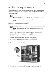
... expansion slots support PCI (Peripheral Component Interconnect) or PCI Express cards. To install an expansion card Note: The illustrations used in this section show the Altos G310 Mk2 server chassis. 1 Observe the ESD precautions and pre-installation procedures described in "ESD precautions" on the mainboard. 4 Remove the tool-less the card bracket lock(1). 5 Pull...
... expansion slots support PCI (Peripheral Component Interconnect) or PCI Express cards. To install an expansion card Note: The illustrations used in this section show the Altos G310 Mk2 server chassis. 1 Observe the ESD precautions and pre-installation procedures described in "ESD precautions" on the mainboard. 4 Remove the tool-less the card bracket lock(1). 5 Pull...

User Manual
Page 64
... setup screen corresponding to the six major BIOS menus: • Main • Advanced • Security • Power • Boot • Exit The parameters on the server to start the system POST (Power On Self Test) process.
... setup screen corresponding to the six major BIOS menus: • Main • Advanced • Security • Power • Boot • Exit The parameters on the server to start the system POST (Power On Self Test) process.


