
Acer Power SX/SXb/SC Service Guide
Page 7
... AcerPower Sx Features 2 AcerPower Sc Features 3 Front Panel 4 Rear Panel 5 AcerPower Sx Main Board Layout 6 AcerPower Sc Main Board Layout 8 Keyboard 9 Cursor keys 9 Lock keys 9 Windows keys 10 Hardware Specifications and Configurations 11 Power Management Function (ACPI support function 21 Chapter 2 System Utilities 23 Entering Setup 24 System Information 26 Product Information 28 Disk Drives 30 IDE Primary/Secondary Channel Master/Slave 31 Onboard Peripherals 33 Power Management 36 Boot Options 38 Date and Time 39 System Security 40 Setting a Password 41 Changing...
... AcerPower Sx Features 2 AcerPower Sc Features 3 Front Panel 4 Rear Panel 5 AcerPower Sx Main Board Layout 6 AcerPower Sc Main Board Layout 8 Keyboard 9 Cursor keys 9 Lock keys 9 Windows keys 10 Hardware Specifications and Configurations 11 Power Management Function (ACPI support function 21 Chapter 2 System Utilities 23 Entering Setup 24 System Information 26 Product Information 28 Disk Drives 30 IDE Primary/Secondary Channel Master/Slave 31 Onboard Peripherals 33 Power Management 36 Boot Options 38 Date and Time 39 System Security 40 Setting a Password 41 Changing...
Acer Power SX/SXb/SC Service Guide
Page 10
... models with AC'97/98 compliant (Embedded in SiS630 chipset) ! On-board serial ports-2 high speed NS16C550 compatible UARTs with integrated L2 cache memory running at 500, 550 and 600 MHz or 533, 667, 733 MHz. ! Universal Serial Bus (USB) ports ! High-speed fax/data PCI modem Human-centric design and ergonomics ! AcerPower Sx Features Performance ! Plug-and Play (PnP) feature ! Low Pin Count (LPC) I/F ! 3 PCI slots + 2 DIMM slots...
... models with AC'97/98 compliant (Embedded in SiS630 chipset) ! On-board serial ports-2 high speed NS16C550 compatible UARTs with integrated L2 cache memory running at 500, 550 and 600 MHz or 533, 667, 733 MHz. ! Universal Serial Bus (USB) ports ! High-speed fax/data PCI modem Human-centric design and ergonomics ! AcerPower Sx Features Performance ! Plug-and Play (PnP) feature ! Low Pin Count (LPC) I/F ! 3 PCI slots + 2 DIMM slots...
Acer Power SX/SXb/SC Service Guide
Page 11
... CODEC with 16 byte FIFOs ! On-board parallel port- High-speed fax/data PCI modem Human-centric design and ergonomics ! Dual in SiS900 10/100BASE-T Ethernet controller (RJ-45 connector) ! Low Pin Count (LPC) I/F ! 3 PCI slots + 2 DIMM slots ! Mini-DIN PS/2 keyboard and mouse ports ! 4 Universal Serial Bus (USB) ports ! Slim, smooth and stylish design Chapter 1 3 USB mouse and keyboard interface ! Software shutdown for ACPI compliant) ! On-board serial port- Plug-and Play (PnP) feature ! One...
... CODEC with 16 byte FIFOs ! On-board parallel port- High-speed fax/data PCI modem Human-centric design and ergonomics ! Dual in SiS900 10/100BASE-T Ethernet controller (RJ-45 connector) ! Low Pin Count (LPC) I/F ! 3 PCI slots + 2 DIMM slots ! Mini-DIN PS/2 keyboard and mouse ports ! 4 Universal Serial Bus (USB) ports ! Slim, smooth and stylish design Chapter 1 3 USB mouse and keyboard interface ! Software shutdown for ACPI compliant) ! On-board serial port- Plug-and Play (PnP) feature ! One...
Acer Power SX/SXb/SC Service Guide
Page 15
PS/2 keyboard and mouse port 2. USB/LAN port 3. Parallel/VGA/serial port 2 4. Floppy disk drive connector NOTE: 8 was for AGP slot, removed when ship out 14. Reset 15. Power LED 19. IDE 2 connector 22. SiS950 chipset 12. Battery 17. PCI slots (three slots) 9. Game/MIDI port 5. Fax/voice modem connector 7. Wake on LAN connector 10. Power Switch 16. ATX power connector Chapter 1 7 BIOS chipset 13. LAN/LED 18. Hard Disk Drive LED connector 20. IDE 1 connector 21. Serial port 1 11. DIMM sockets (two sockets) 23. 1. Audio/CD connector 6. CPU socket...
PS/2 keyboard and mouse port 2. USB/LAN port 3. Parallel/VGA/serial port 2 4. Floppy disk drive connector NOTE: 8 was for AGP slot, removed when ship out 14. Reset 15. Power LED 19. IDE 2 connector 22. SiS950 chipset 12. Battery 17. PCI slots (three slots) 9. Game/MIDI port 5. Fax/voice modem connector 7. Wake on LAN connector 10. Power Switch 16. ATX power connector Chapter 1 7 BIOS chipset 13. LAN/LED 18. Hard Disk Drive LED connector 20. IDE 1 connector 21. Serial port 1 11. DIMM sockets (two sockets) 23. 1. Audio/CD connector 6. CPU socket...
Acer Power SX/SXb/SC Service Guide
Page 19
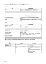
...in BIOS Setup is booting to enter BIOS Setup Utility. BIOS Item BIOS code programmer BIOS version BIOS ROM type BIOS ROM size BIOS ROM package Support protocol Boot from 1.2 to 1.4 GHz and above Celeron 850/950 MHz , 1.1/1.2 GHz 0 MHz (If Stop CPU Clock in Sleep State in BIOS Setup Utility main menu screen, the Advanced Options menu then appears. The items on the Advanced Options menu are: Memory/Cache Options PnP/PCI Options Chapter 1 11 Hardware Specifications and Configurations Processor Type Socket Speed Item Minimum operating speed Voltage Specification AcerPower Sx: Intel...
...in BIOS Setup is booting to enter BIOS Setup Utility. BIOS Item BIOS code programmer BIOS version BIOS ROM type BIOS ROM size BIOS ROM package Support protocol Boot from 1.2 to 1.4 GHz and above Celeron 850/950 MHz , 1.1/1.2 GHz 0 MHz (If Stop CPU Clock in Sleep State in BIOS Setup Utility main menu screen, the Advanced Options menu then appears. The items on the Advanced Options menu are: Memory/Cache Options PnP/PCI Options Chapter 1 11 Hardware Specifications and Configurations Processor Type Socket Speed Item Minimum operating speed Voltage Specification AcerPower Sx: Intel...
Acer Power SX/SXb/SC Service Guide
Page 35
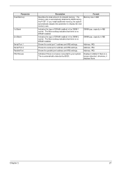
... there is a mouse connected to display the new memory size. otherwise, it displays None. Shows the serial port 1 address and IRQ settings. Shows the serial port 2 address and IRQ settings. Indicates if there is no DRAM installed. Format Memory size in MB DIMM type, capacity in MB DIMM type, capacity in the DIMM 2 socket. The None setting indicates that there is automatically detected by BIOS during the POST...
... there is a mouse connected to display the new memory size. otherwise, it displays None. Shows the serial port 1 address and IRQ settings. Shows the serial port 2 address and IRQ settings. Indicates if there is no DRAM installed. Format Memory size in MB DIMM type, capacity in MB DIMM type, capacity in the DIMM 2 socket. The None setting indicates that there is automatically detected by BIOS during the POST...
Acer Power SX/SXb/SC Service Guide
Page 40
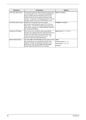
... the use . Enabling this parameter to Auto, the BIOS utility automatically detects if the installed hard disk supports the function, it allows data transfer in better hard disk performance. Options Auto or Disabled Enabled or Disabled Auto, Mode 0, 1, 2, 3 or 4 Auto Multiword Mode 0, 1, 2 Ultra Mode 0, 1, 2, 3, 4 Disabled 32 Chapter 2 If you set to Auto, the BIOS utility automatically detects if the installed hard disk drive supports the Block Mode function. This enhanced IDE feature works only under DOS, Windows 3.x, Windows 95/98, Windows...
... the use . Enabling this parameter to Auto, the BIOS utility automatically detects if the installed hard disk supports the function, it allows data transfer in better hard disk performance. Options Auto or Disabled Enabled or Disabled Auto, Mode 0, 1, 2, 3 or 4 Auto Multiword Mode 0, 1, 2 Ultra Mode 0, 1, 2, 3, 4 Disabled 32 Chapter 2 If you set to Auto, the BIOS utility automatically detects if the installed hard disk drive supports the Block Mode function. This enhanced IDE feature works only under DOS, Windows 3.x, Windows 95/98, Windows...

Acer Power SX/SXb/SC Service Guide
Page 44
... mode after inactivity of 1 to normal operation. Options Enabled or Disabled 1 to Suspend mode when the power switch is installed in boldface are the default and suggested settings. Settings in ACPI mode, the operating system will resume the system to 15 minutes, depending on AC/Power Failure Enabled ] The following screen shows the Power Management parameters and their default settings: Power Management Power Management Mode Enabled ] IDE Hard Disk Standby Timer OFF] System Sleep Timer 30] Minute(s) Sleep Mode Suspend] Power Switch < 4 sec Power Off] System wake...
... mode after inactivity of 1 to normal operation. Options Enabled or Disabled 1 to Suspend mode when the power switch is installed in boldface are the default and suggested settings. Settings in ACPI mode, the operating system will resume the system to 15 minutes, depending on AC/Power Failure Enabled ] The following screen shows the Power Management parameters and their default settings: Power Management Power Management Mode Enabled ] IDE Hard Disk Standby Timer OFF] System Sleep Timer 30] Minute(s) Sleep Mode Suspend] Power Switch < 4 sec Power Off] System wake...
Acer Power SX/SXb/SC Service Guide
Page 71
Index of Error Symptoms ! Index of Error Codes and Error Beeps ! Index of Error Messages ! Undetermined Problems Chapter 4 Chapter 4 63 Power-On Self-Test (POST) ! Troubleshooting This chapter provides troubleshooting information for AcerPower Sx model: !
Index of Error Symptoms ! Index of Error Codes and Error Beeps ! Index of Error Messages ! Undetermined Problems Chapter 4 Chapter 4 63 Power-On Self-Test (POST) ! Troubleshooting This chapter provides troubleshooting information for AcerPower Sx model: !
Acer Power SX/SXb/SC Service Guide
Page 72
... numeric co-processor and cache memory subsystem ! Microprocessor with battery backup ! Interrupt system ! RAM subsystem ! Onboard serial interface controller ! Embedded hard disk interface and one diskette drive interface ! Keyboard and auxiliary device controllers ! PS/2-compatible keyboard port ! Power-On Self-Test (POST) Each time you turn on the system, the Power-on password option. The Power-On Self Test (POST) is fatal. Serial ports ! Parallel ports ! The main components on the main board that boots the system...
... numeric co-processor and cache memory subsystem ! Microprocessor with battery backup ! Interrupt system ! RAM subsystem ! Onboard serial interface controller ! Embedded hard disk interface and one diskette drive interface ! Keyboard and auxiliary device controllers ! PS/2-compatible keyboard port ! Power-On Self-Test (POST) Each time you turn on the system, the Power-on password option. The Power-On Self Test (POST) is fatal. Serial ports ! Parallel ports ! The main components on the main board that boots the system...
Acer Power SX/SXb/SC Service Guide
Page 73
... CMOS default setting 3. To initialize the RTC time base, turn the system on a debug board. Tests keyboard controller (8041/8042) 2. If it is currently running. NOTE: These interrupts are disabled in CMOS RAM. DRAM type determination 1. System shadow RAM 1. Check CPU ID, dispatch shutdown Path. If it jumps around the initialization procedure to real mode from exiting BIOS setup. Then it is a warm boot, the chip initialization and memory test is...
... CMOS default setting 3. To initialize the RTC time base, turn the system on a debug board. Tests keyboard controller (8041/8042) 2. If it is currently running. NOTE: These interrupts are disabled in CMOS RAM. DRAM type determination 1. System shadow RAM 1. Check CPU ID, dispatch shutdown Path. If it jumps around the initialization procedure to real mode from exiting BIOS setup. Then it is a warm boot, the chip initialization and memory test is...

Acer Power SX/SXb/SC Service Guide
Page 74
... ROM into shadow RAM Process VGA shadow region Check CPU brand, ID and external frequency 1. Tests and initializes FDD 2. The FDD LED should flash once and its I/O ROM or corresponding initialization program. Hook INT 1CH for user pressing CTRL + ALT DEL. Tests HDD controller Displays POST status Rehook INT 1CH for Quiet Boot 1. Keyboard device initialization 1. I/O ROM is an optional extension of the BIOS located on an installed add-on card as part of the I /O ROMs...
... ROM into shadow RAM Process VGA shadow region Check CPU brand, ID and external frequency 1. Tests and initializes FDD 2. The FDD LED should flash once and its I/O ROM or corresponding initialization program. Hook INT 1CH for user pressing CTRL + ALT DEL. Tests HDD controller Displays POST status Rehook INT 1CH for Quiet Boot 1. Keyboard device initialization 1. I/O ROM is an optional extension of the BIOS located on an installed add-on card as part of the I /O ROMs...
Acer Power SX/SXb/SC Service Guide
Page 76
.../2 keyboard 4. Remove all power supply voltages, switch, and jumper settings before you replace the main board. Also check the power supply voltages if you have done so, you must run the diagnostics program tests but did receive a POST error message, use "POST Error Messages List" to diagnose system problems. If you did not receive any error message, look for processor is correct. 2. Enter BIOS Setup and load the default settings. 2. Ensure the system configuration set correctly. 1. Memory module 3. Diskette drive cable/connection...
.../2 keyboard 4. Remove all power supply voltages, switch, and jumper settings before you replace the main board. Also check the power supply voltages if you have done so, you must run the diagnostics program tests but did receive a POST error message, use "POST Error Messages List" to diagnose system problems. If you did not receive any error message, look for processor is correct. 2. Enter BIOS Setup and load the default settings. 2. Ensure the system configuration set correctly. 1. Memory module 3. Diskette drive cable/connection...

Acer Power SX/SXb/SC Service Guide
Page 77
... 2. Flash BIOS 1. IDE hard disk drive cable/connection. 5. System board 1. Remove all adapter cards that are NOT factoryinstalled, then reboot the system. 1. Enter BIOS Setup and load the default settings. 3. Load default settings in Setup. 2. Enter BIOS Setup and set the Reset Resource Assignments of the PnP/PCI Options to Yes, then reboot the system. 3. Press ESC to reject NMI error or press any key to reboot Insert system diskette and press ENTER key to reboot Action/FRU 1. Enter BIOS Setup and load the default settings. 2. IDE hard disk drive power. 4. BIOS...
... 2. Flash BIOS 1. IDE hard disk drive cable/connection. 5. System board 1. Remove all adapter cards that are NOT factoryinstalled, then reboot the system. 1. Enter BIOS Setup and load the default settings. 3. Load default settings in Setup. 2. Enter BIOS Setup and set the Reset Resource Assignments of the PnP/PCI Options to Yes, then reboot the system. 3. Press ESC to reject NMI error or press any key to reboot Insert system diskette and press ENTER key to reboot Action/FRU 1. Enter BIOS Setup and load the default settings. 2. IDE hard disk drive power. 4. BIOS...
Acer Power SX/SXb/SC Service Guide
Page 79
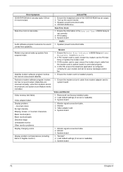
... Options of hard disk LED connector. 2. Chapter 4 71 Error Symptom Action/FRU Diskette drive read and there are no messages are set to light, but works normally. 1. Diskette drive cable. 4. Diskette drive LED comes on it . Diskette 2. Hard disk drive cable. 3. CD/DVD-ROM Drive NOTE: Ensure CD/DVD-ROM drive is configured correctly in BIOS Setup, cable/jumper are set correctly and its eject button is installed properly. 3. Software displays a reading CD/DVD error. 1. Diskette drive connection/cable 4. Diskette drive 5. Diskette drive cable 4. Hard disk drive...
... Options of hard disk LED connector. 2. Chapter 4 71 Error Symptom Action/FRU Diskette drive read and there are no messages are set to light, but works normally. 1. Diskette drive cable. 4. Diskette drive LED comes on it . Diskette 2. Hard disk drive cable. 3. CD/DVD-ROM Drive NOTE: Ensure CD/DVD-ROM drive is configured correctly in BIOS Setup, cable/jumper are set correctly and its eject button is installed properly. 3. Software displays a reading CD/DVD error. 1. Diskette drive connection/cable 4. Diskette drive 5. Diskette drive cable 4. Hard disk drive...
Acer Power SX/SXb/SC Service Guide
Page 80
... listed above (including blank or illegible monitor). Speaker power/connection/cable. 4. Ensure the modem card is readable). 3. System board 72 Chapter 4 Real-Time Clock 1. Monitor 3. Real-time clock is readable). 3. voice from speakers. Remove all non-factory-installed cards. 2. Load default settings (if screen is inaccurate. Error Symptom CD/DVD-ROM drive can play audio CD but has no sound output. (Data files are received normally; Ensure the information in BIOS Setup or Power Management is set to Enabled. 2. Video adapter...
... listed above (including blank or illegible monitor). Speaker power/connection/cable. 4. Ensure the modem card is readable). 3. System board 72 Chapter 4 Real-Time Clock 1. Monitor 3. Real-time clock is readable). 3. voice from speakers. Remove all non-factory-installed cards. 2. Load default settings (if screen is inaccurate. Error Symptom CD/DVD-ROM drive can play audio CD but has no sound output. (Data files are received normally; Ensure the information in BIOS Setup or Power Management is set to Enabled. 2. Video adapter...
Acer Power SX/SXb/SC Service Guide
Page 82
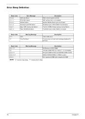
...: "2" means long beep, "1" means short beep 74 Chapter 4 Shutdown byte in RTC/CMOS r/w test failure The first 128KB of spec. before 1.1 or unavailable Mix EDO DIMM w/ SPD and SDRAM DIMM w/ SPD 66MHz SDRAM DIMM in flash ROM is corrupted Beep Code 2-1-1 1-1 Warning Message VGA Com Port Boot Description Video buffer error Console does not exist and message displayed to terminal Beep Code 2-2-1-1-1 2-2 2-2-2-1-1 2-2-2-1-1-1 2-2-2-1 Warning Message Description No Memory or EDO...
...: "2" means long beep, "1" means short beep 74 Chapter 4 Shutdown byte in RTC/CMOS r/w test failure The first 128KB of spec. before 1.1 or unavailable Mix EDO DIMM w/ SPD and SDRAM DIMM w/ SPD 66MHz SDRAM DIMM in flash ROM is corrupted Beep Code 2-1-1 1-1 Warning Message VGA Com Port Boot Description Video buffer error Console does not exist and message displayed to terminal Beep Code 2-2-1-1-1 2-2 2-2-2-1-1 2-2-2-1-1-1 2-2-2-1 Warning Message Description No Memory or EDO...
Acer Power SX/SXb/SC Service Guide
Page 114
... IDE1 connector 78 IDE2 connector 78 IDSEL 17 Interface audio 15 Floppy disk drive 16 IDE 15 Video 14 Intrusion jumper 78, 80 IRQ Assignment Map 18 J Jumper and Connector Information 77 Jumpers 77 K keyboard 9 cursor keys 9 lock keys 9 windows-keys 10 L LAN LED jumper 78, 80 Load Default Settings 47 M Machine Disassembly and Replacement 51 Main board Removing 60 Main board Layout 6 Mechanical Specifications 19 Memory size 13 system 13 Memory Address Map 17 Memory/Cache Options 43 external cache 44 internal cache...
... IDE1 connector 78 IDE2 connector 78 IDSEL 17 Interface audio 15 Floppy disk drive 16 IDE 15 Video 14 Intrusion jumper 78, 80 IRQ Assignment Map 18 J Jumper and Connector Information 77 Jumpers 77 K keyboard 9 cursor keys 9 lock keys 9 windows-keys 10 L LAN LED jumper 78, 80 Load Default Settings 47 M Machine Disassembly and Replacement 51 Main board Removing 60 Main board Layout 6 Mechanical Specifications 19 Memory size 13 system 13 Memory Address Map 17 Memory/Cache Options 43 external cache 44 internal cache...
Acer Power SX/SXb/SC Service Guide
Page 115
... Controller 35 USB Legacy Mode 35 Online Support Information 103 Overview 1 P Parallel Port 16 Parallel/VGA/serial port 2 connector 78 Password bypassing 42 changing 42 removing 42 setting 41 PCI INTx# 17 PCI Slot IRQ 17 PnP PCI Options Graphics Aperture Size 45 IRQ Sharing 45 PCI IRQ Setting 45 Plug and Play OS 46 Reset Resource Assignments 46 VGA Palette Snoop 45 ports left panel 5 POST 64 Post Check Points 65 POST Error Messages List 64 Power LED jumper 78 Power Management...
... Controller 35 USB Legacy Mode 35 Online Support Information 103 Overview 1 P Parallel Port 16 Parallel/VGA/serial port 2 connector 78 Password bypassing 42 changing 42 removing 42 setting 41 PCI INTx# 17 PCI Slot IRQ 17 PnP PCI Options Graphics Aperture Size 45 IRQ Sharing 45 PCI IRQ Setting 45 Plug and Play OS 46 Reset Resource Assignments 46 VGA Palette Snoop 45 ports left panel 5 POST 64 Post Check Points 65 POST Error Messages List 64 Power LED jumper 78 Power Management...

Acer Power SX/SXb/SC Service Guide
Page 116
... 26 Internal cache size 26 parallel port 27 Processor 26 Processor speed 26 PS/2 mouse 27 serial port 1 27 serial port 2 27 total memory 27 System Security disk drive controller 40 floppy disk drive 40 hard disk drive 40 Processor Serial Number 40 Supervisor password 40 User password 40 System Specifications 1 design 2, 3 Features 2 System Utilities 23 Abort Settings Change 48 Advanced Options 43 Boot Options 38 Date 39 Disk Drives 30 Exiting Setup 49 108 Load Default Settings 47 Memory/Cache Options 43 Onboard Peripherals 33 PnP/PCI Options 45 Power Management 36...
... 26 Internal cache size 26 parallel port 27 Processor 26 Processor speed 26 PS/2 mouse 27 serial port 1 27 serial port 2 27 total memory 27 System Security disk drive controller 40 floppy disk drive 40 hard disk drive 40 Processor Serial Number 40 Supervisor password 40 User password 40 System Specifications 1 design 2, 3 Features 2 System Utilities 23 Abort Settings Change 48 Advanced Options 43 Boot Options 38 Date 39 Disk Drives 30 Exiting Setup 49 108 Load Default Settings 47 Memory/Cache Options 43 Onboard Peripherals 33 PnP/PCI Options 45 Power Management 36...


