
Power Sc User's Guide
Page 2
AcerPower SC User's guide Changes may be incorporated in any form or by any person of purchase information in this manual or supplementary documents and publications. Record the model number, serial number, purchase date, and place of such revision or changes. This company makes no representations or warranties, either expressed or implied, with respect to your unit should include the serial number, model number, and purchase information...
AcerPower SC User's guide Changes may be incorporated in any form or by any person of purchase information in this manual or supplementary documents and publications. Record the model number, serial number, purchase date, and place of such revision or changes. This company makes no representations or warranties, either expressed or implied, with respect to your unit should include the serial number, model number, and purchase information...

Power Sc User's Guide
Page 3
... and, if not installed and used in accordance with the instructions, may be determined by turning the device off and on a circuit different from that interference will not occur in a residential installation. This device generates, uses, and can be attached...operate this equipment. iii Notices FCC notice This device has been tested and found to comply with noncertified peripherals is likely to result in interference to radio and TV reception. Operation with the limits for help Notice: Shield cables All connections to other computing devices must be made using shielded cables...
... and, if not installed and used in accordance with the instructions, may be determined by turning the device off and on a circuit different from that interference will not occur in a residential installation. This device generates, uses, and can be attached...operate this equipment. iii Notices FCC notice This device has been tested and found to comply with noncertified peripherals is likely to result in interference to radio and TV reception. Operation with the limits for help Notice: Shield cables All connections to other computing devices must be made using shielded cables...

Power Sc User's Guide
Page 5
... of the equipment plugged into this product yourself, as they may touch dangerous voltage points or short out parts that the total rating of power available, consult your dealer or local power company. Refer all servicing to service this product through cabinet slots as opening or removing covers may fall, causing serious damage to protect it from the type of any...
... of the equipment plugged into this product yourself, as they may touch dangerous voltage points or short out parts that the total rating of power available, consult your dealer or local power company. Refer all servicing to service this product through cabinet slots as opening or removing covers may fall, causing serious damage to protect it from the type of any...
Power Sc User's Guide
Page 6
... extensive work by a qualified technician to restore the product to a qualified serviceman. Batteries may present a risk of power supply cord set (provided in your accessories box) for service. Do not disassemble or dispose of them away from children and dispose of used batteries promptly. 14 Use only the proper type of fire or explosion. It should be a detachable type: UL listed/CSA certified, type SPT...
... extensive work by a qualified technician to restore the product to a qualified serviceman. Batteries may present a risk of power supply cord set (provided in your accessories box) for service. Do not disassemble or dispose of them away from children and dispose of used batteries promptly. 14 Use only the proper type of fire or explosion. It should be a detachable type: UL listed/CSA certified, type SPT...
Power Sc User's Guide
Page 9
... Features Front panel Rear panel USB Keyboard Programmable keys Internet/Suspend keys Multimedia keys Volume control/Mute Cursor keys Lock keys Windows keys Mouse Disk drives 3.5-inch floppy disk drive CD-ROM drive Hard disk drive 7 9 10 11 12 13 13 13 14 14 14 15 16 17 17 17 19 3 Setting up your computer Arranging a comfortable work area Adjusting your chair Positioning your PC Positioning your monitor Positioning your keyboard Positioning your mouse Connecting peripherals Mouse USB Keyboard Monitor Power cable Connecting options Printer Network Modem Multimedia devices USB devices 21...
... Features Front panel Rear panel USB Keyboard Programmable keys Internet/Suspend keys Multimedia keys Volume control/Mute Cursor keys Lock keys Windows keys Mouse Disk drives 3.5-inch floppy disk drive CD-ROM drive Hard disk drive 7 9 10 11 12 13 13 13 14 14 14 15 16 17 17 17 19 3 Setting up your computer Arranging a comfortable work area Adjusting your chair Positioning your PC Positioning your monitor Positioning your keyboard Positioning your mouse Connecting peripherals Mouse USB Keyboard Monitor Power cable Connecting options Printer Network Modem Multimedia devices USB devices 21...

Power Sc User's Guide
Page 10
x Turning on your computer Turning off your computer 34 36 4 Upgrading your computer Installation precautions ESD precautions Preinstallation instructions Post-installation instructions Opening your computer Removing the cover Replacing the cover Mainboard CPU frequency table Installing additional memory Installing a DIMM Removing a DIMM Reconfiguring your computer Upgrading the CPU Replacing the hard disk Installing an expansion card 37 39 39 39 40 41 41 43 45 47 48 48 49 49 50 52 57
x Turning on your computer Turning off your computer 34 36 4 Upgrading your computer Installation precautions ESD precautions Preinstallation instructions Post-installation instructions Opening your computer Removing the cover Replacing the cover Mainboard CPU frequency table Installing additional memory Installing a DIMM Removing a DIMM Reconfiguring your computer Upgrading the CPU Replacing the hard disk Installing an expansion card 37 39 39 39 40 41 41 43 45 47 48 48 49 49 50 52 57
Power Sc User's Guide
Page 13
3 Package contents Before you unpack your computer, make sure that you have enough space to set up your dealer immediately AcerPower SC USB keyboard Mouse Power cable User's guide Other user documentation and third-party software If any of the following items are missing or damaged, contact your computer. Carefully unpack the carton and remove the contents.
3 Package contents Before you unpack your computer, make sure that you have enough space to set up your dealer immediately AcerPower SC USB keyboard Mouse Power cable User's guide Other user documentation and third-party software If any of the following items are missing or damaged, contact your computer. Carefully unpack the carton and remove the contents.

Power Sc User's Guide
Page 19
.../3D graphics accelerator (embedded in SiS630ET chipset) Integrated 3D positional audio controller (embedded in SiS630ET chipset) Audio-in/Line-in, Audio-out/Line-out, Mic-in, and Game/MIDI interfaces Connectivity PS/2 mouse and USB keyboard interface One serial port, one parallel port, and one VGA port Universal Serial Bus (USB) ports Integrated 10Base-T/100Base-TX network support with remote wake-up function (embedded in SiS630ET chipset) High-speed fax/data PCI modem (optional)
.../3D graphics accelerator (embedded in SiS630ET chipset) Integrated 3D positional audio controller (embedded in SiS630ET chipset) Audio-in/Line-in, Audio-out/Line-out, Mic-in, and Game/MIDI interfaces Connectivity PS/2 mouse and USB keyboard interface One serial port, one parallel port, and one VGA port Universal Serial Bus (USB) ports Integrated 10Base-T/100Base-TX network support with remote wake-up function (embedded in SiS630ET chipset) High-speed fax/data PCI modem (optional)

Power Sc User's Guide
Page 21
...'s rear panel consists of the following: No. 1 2 3 4 5 6 7 8 9 Component System main power switch Voltage selector System power socket Fan PS/2 keyboard port PS/2 mouse port LAN port USB ports Serial 2 port No. 10 11 12 13 14 15 16 17 Component Parallel port VGA/Monitor port Speaker-out/Line-out port Game/MIDI port Line-in port Microphone-in some regions. For information on how to connect the peripherals, see "Connecting peripherals" on page 25 and "Connecting options" on...
...'s rear panel consists of the following: No. 1 2 3 4 5 6 7 8 9 Component System main power switch Voltage selector System power socket Fan PS/2 keyboard port PS/2 mouse port LAN port USB ports Serial 2 port No. 10 11 12 13 14 15 16 17 Component Parallel port VGA/Monitor port Speaker-out/Line-out port Game/MIDI port Line-in port Microphone-in some regions. For information on how to connect the peripherals, see "Connecting peripherals" on page 25 and "Connecting options" on...
Power Sc User's Guide
Page 23
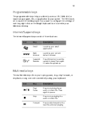
... button to put the system to launch the media player. The fifth key is set to sleep. 13 Programmable keys The programmable keys help you directly access a URL (Web site) or launch any program, file, or application in your Windows desktop. If you want to start playing. Icon Key Play/ Pause Description Press to configure the settings of three buttons: Icon Key Email Description Launches your keyboard...
... button to put the system to launch the media player. The fifth key is set to sleep. 13 Programmable keys The programmable keys help you directly access a URL (Web site) or launch any program, file, or application in your Windows desktop. If you want to start playing. Icon Key Play/ Pause Description Press to configure the settings of three buttons: Icon Key Email Description Launches your keyboard...
Power Sc User's Guide
Page 29
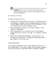
... the CD tray. When cleaning CDs, use a clean, dust-free cloth and wipe in use to the Cleaning Kit for support. Cleaning Kits can affect the data on the disc, impair the disc lens reader on the CD-ROM drive, or stop the computer from the center to replace your hard disk or upgrade it, contact your CD-ROM drive periodically. When handling CDs, always hold...
... the CD tray. When cleaning CDs, use a clean, dust-free cloth and wipe in use to the Cleaning Kit for support. Cleaning Kits can affect the data on the disc, impair the disc lens reader on the CD-ROM drive, or stop the computer from the center to replace your hard disk or upgrade it, contact your CD-ROM drive periodically. When handling CDs, always hold...

Power Sc User's Guide
Page 35
Mouse Plug the mouse cable into the PS/2 mouse port or USB port located on the rear panel of your computer is easy. Connecting the PS/2 mouse Connecting the USB mouse For the most part, you only have four things to connect: the mouse, the USB keyboard, the monitor and the power cable. 25 Connecting peripherals Setting up your computer.
Mouse Plug the mouse cable into the PS/2 mouse port or USB port located on the rear panel of your computer is easy. Connecting the PS/2 mouse Connecting the USB mouse For the most part, you only have four things to connect: the mouse, the USB keyboard, the monitor and the power cable. 25 Connecting peripherals Setting up your computer.
Power Sc User's Guide
Page 40
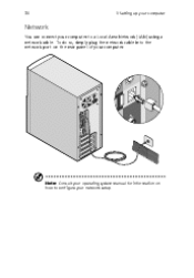
To do so, simply plug the network cable into the network port on how to a Local Area Network (LAN) using a network cable. 30 3 Setting up your computer Network You can connect your computer to configure your computer. Note: Consult your operating system manual for information on the rear panel of your network setup.
To do so, simply plug the network cable into the network port on how to a Local Area Network (LAN) using a network cable. 30 3 Setting up your computer Network You can connect your computer to configure your computer. Note: Consult your operating system manual for information on the rear panel of your network setup.

Power Sc User's Guide
Page 44
Locate and turn on the main power switch on the rear panel of your computer such as the monitor, printer, fax, speakers, etc. To turn on your computer: 1 2 Turn on and get to your computer. 34 3 Setting up your computer Turning on your computer After connecting the necessary peripherals and plugging in the power cable, you are now ready to turn the computer on all peripherals connected to work.
Locate and turn on the main power switch on the rear panel of your computer such as the monitor, printer, fax, speakers, etc. To turn on your computer: 1 2 Turn on and get to your computer. 34 3 Setting up your computer Turning on your computer After connecting the necessary peripherals and plugging in the power cable, you are now ready to turn the computer on all peripherals connected to work.
Power Sc User's Guide
Page 49
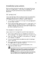
... start installing the components may cause serious damage. Warning! 39 Installation precautions Before you install any system component, we recommend that block access to the DIMM sockets or component connector. Not turning off your processor, disk drives, expansion boards, and other components. ESD precautions Electrostatic discharge (ESD) can damage your computer and all cables from its protective packaging until you are a qualified service...
... start installing the components may cause serious damage. Warning! 39 Installation precautions Before you install any system component, we recommend that block access to the DIMM sockets or component connector. Not turning off your processor, disk drives, expansion boards, and other components. ESD precautions Electrostatic discharge (ESD) can damage your computer and all cables from its protective packaging until you are a qualified service...

Power Sc User's Guide
Page 50
See "Mainboard" on your computer Post-installation instructions Observe the following after installing a system component: 1 2 3 4 5 See to the stepby-step instructions in their respective sections. Replace any expansion boards or peripherals that the components are installed according to it that you have set all the required jumpers. Replace the computer cover. Make sure you removed earlier. Connect the necessary cables and turn on page 45 for the correct jumper settings. 40 4 Upgrading your computer.
See "Mainboard" on your computer Post-installation instructions Observe the following after installing a system component: 1 2 3 4 5 See to the stepby-step instructions in their respective sections. Replace any expansion boards or peripherals that the components are installed according to it that you have set all the required jumpers. Replace the computer cover. Make sure you removed earlier. Connect the necessary cables and turn on page 45 for the correct jumper settings. 40 4 Upgrading your computer.

Power Sc User's Guide
Page 51
Read the "Preinstallation instructions" on a flat, steady surface. Removing the cover 1 2 3 Turn off your computer before you can install additional components. You will need to it. 41 Opening your computer Caution: Before you proceed, make sure that you have turned off the system power and unplug all peripherals connected to open your computer and all cables. Place the system unit on page 39. See the following section for instructions. Remove the four screws from the rear panel. Set the screws aside. You need them when replacing the housing cover.
Read the "Preinstallation instructions" on a flat, steady surface. Removing the cover 1 2 3 Turn off your computer before you can install additional components. You will need to it. 41 Opening your computer Caution: Before you proceed, make sure that you have turned off the system power and unplug all peripherals connected to open your computer and all cables. Place the system unit on page 39. See the following section for instructions. Remove the four screws from the rear panel. Set the screws aside. You need them when replacing the housing cover.

Power Sc User's Guide
Page 56
...CN12 CN13 CN16 CN18 CN20 CN21 CN22 CN23 JP1 Description PS/2 connectors USB/LAN connectors ATX power connector 4 Upgrading your computer Printer/VGA/COM2 connectors IDE2 connector IDE1 connector Game/MIDI port 12-pin AC'97 connector Audio CD connector FDD connector HDD LED connector Fax voice modem connector Wake-on LAN c onnector RF connector Slim CD-ROM connector Optional USB ports Audio-in connector 1-2: Disable onboard Codec 2-3: Enable onboard Codec JP2 JP3 Power LED connector 1-2 and 4-5: 4M flash ROM 2-3 and 5-6: 2M flash ROM JP4 JP5 JP6 Reset connector Intrusion LAN LED connector
...CN12 CN13 CN16 CN18 CN20 CN21 CN22 CN23 JP1 Description PS/2 connectors USB/LAN connectors ATX power connector 4 Upgrading your computer Printer/VGA/COM2 connectors IDE2 connector IDE1 connector Game/MIDI port 12-pin AC'97 connector Audio CD connector FDD connector HDD LED connector Fax voice modem connector Wake-on LAN c onnector RF connector Slim CD-ROM connector Optional USB ports Audio-in connector 1-2: Disable onboard Codec 2-3: Enable onboard Codec JP2 JP3 Power LED connector 1-2 and 4-5: 4M flash ROM 2-3 and 5-6: 2M flash ROM JP4 JP5 JP6 Reset connector Intrusion LAN LED connector
Power Sc User's Guide
Page 59
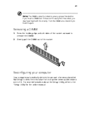
Run Setup to insert it again. Turn the DIMM around and try to view the new value for total system memory and make a note of the socket outward to the "Setup Utility"in the online manual. Gently pull the DIMM out of memory installed. For more information about the Setup Utility, refer to release the DIMM. Removing a DIMM 1 2 Press the holding clips on both sides...
Run Setup to insert it again. Turn the DIMM around and try to view the new value for total system memory and make a note of the socket outward to the "Setup Utility"in the online manual. Gently pull the DIMM out of memory installed. For more information about the Setup Utility, refer to release the DIMM. Removing a DIMM 1 2 Press the holding clips on both sides...

Power Sc User's Guide
Page 60
... board supports Pentium III and Celeron processors and future Intel processors. Make sure that pin 1 (indicated by a notched corner) of the CPU connects to a 370-pin socket form factor instead of the socket. Follow these steps to lock the new CPU into the socket. Disconnect the 3-pin and 2-pin fan/heatsink cables from the system board. 50 4 Upgrading your CPU: 1 2 3 4 5 Remove the cover as shown on page 39. See section "Installation...
... board supports Pentium III and Celeron processors and future Intel processors. Make sure that pin 1 (indicated by a notched corner) of the CPU connects to a 370-pin socket form factor instead of the socket. Follow these steps to lock the new CPU into the socket. Disconnect the 3-pin and 2-pin fan/heatsink cables from the system board. 50 4 Upgrading your CPU: 1 2 3 4 5 Remove the cover as shown on page 39. See section "Installation...


