
Acer AT110 F2 Service Guide
Page 6
... / Removal Install a hot-swap power supply module 25 26 26 27 28 29 30 30 31 32 32 CABLE ROUTING Cable Routing image 33 33 BIOS SETUP Main Menu Advanced Menu Processor Configuration Memory Configuration Advanced Chipset Configuration ACPI Configuration SATA Controller Configuration PCI Configuration USB Configuration Legacy Device Configuration Power...
... / Removal Install a hot-swap power supply module 25 26 26 27 28 29 30 30 31 32 32 CABLE ROUTING Cable Routing image 33 33 BIOS SETUP Main Menu Advanced Menu Processor Configuration Memory Configuration Advanced Chipset Configuration ACPI Configuration SATA Controller Configuration PCI Configuration USB Configuration Legacy Device Configuration Power...
Acer AT110 F2 Service Guide
Page 7
Console Redirection Hardware Monitor Security Menu Setting a System Password Changing a System Password Removing a System Password Server Management Menu System Information Event Log Configuration Boot Option Menu Boot Manager Menu Exit Menu 50 52 53 54 54 54 55 56 57 59 60 61 TROUBLESHOOTING Error Symptoms List 62 62 BIOS BEEP CODES BIOS Beep Codes Table PEI Beep Codes DXE Beep Codes BIOS Recovery Instruction 65 65 65 65 65 BIOS POST ERROR MESSAGES LIST BIOS POST error message list PEI Phase DXE Phase 68 68 68 69 UNDETERMINED PROBLEMS 71 3
Console Redirection Hardware Monitor Security Menu Setting a System Password Changing a System Password Removing a System Password Server Management Menu System Information Event Log Configuration Boot Option Menu Boot Manager Menu Exit Menu 50 52 53 54 54 54 55 56 57 59 60 61 TROUBLESHOOTING Error Symptoms List 62 62 BIOS BEEP CODES BIOS Beep Codes Table PEI Beep Codes DXE Beep Codes BIOS Recovery Instruction 65 65 65 65 65 BIOS POST ERROR MESSAGES LIST BIOS POST error message list PEI Phase DXE Phase 68 68 68 69 UNDETERMINED PROBLEMS 71 3

Acer AT110 F2 Service Guide
Page 28
Clear CMOS jumper (CLR_CMOS1) 1-2 Close: Normal operation. (Default) 2-3 Close: Clear CMOS data. 24 Clear Password Jumper (PWD_JP1) 1-2 Close: Normal operation. (Default) 2-3 Close: Clear password. Motherboard Jumper Setting Item 1 2 3 4 5 Description Vcore voltage test jumper (VBoot_SEL) 1-2 Close: Factory test. 2-3 Close: Intel default. (Default) BIOS recovery jumper (BIOS_JP1) 1-2 Close: Normal operation. (Default) 2-3 Close: BIOS recovery mode. ME Recovery Jumper (MFG_F_JP1) 1-2 Close: Enable ME recovery. (Default) 2-3 Close: Disable ME recovery.
Clear CMOS jumper (CLR_CMOS1) 1-2 Close: Normal operation. (Default) 2-3 Close: Clear CMOS data. 24 Clear Password Jumper (PWD_JP1) 1-2 Close: Normal operation. (Default) 2-3 Close: Clear password. Motherboard Jumper Setting Item 1 2 3 4 5 Description Vcore voltage test jumper (VBoot_SEL) 1-2 Close: Factory test. 2-3 Close: Intel default. (Default) BIOS recovery jumper (BIOS_JP1) 1-2 Close: Normal operation. (Default) 2-3 Close: BIOS recovery mode. ME Recovery Jumper (MFG_F_JP1) 1-2 Close: Enable ME recovery. (Default) 2-3 Close: Disable ME recovery.
Acer AT110 F2 Service Guide
Page 33
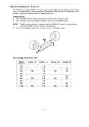
... the DIMM module. Reverse the installation steps when you wish to lock the DIMM module. Memory Installation / Removal The motherboard supports DDR3 memory modules, whereby BIOS will automatically detect memory capacity and specifications. Memory modules are designed so that they can differ with each slot. Installation step: 1. DIMM must be populated...
... the DIMM module. Reverse the installation steps when you wish to lock the DIMM module. Memory Installation / Removal The motherboard supports DDR3 memory modules, whereby BIOS will automatically detect memory capacity and specifications. Memory modules are designed so that they can differ with each slot. Installation step: 1. DIMM must be populated...
Acer AT110 F2 Service Guide
Page 38
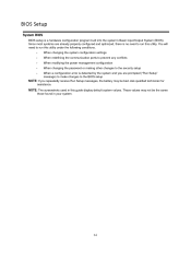
...are prompted ("Run Setup" message) to make changes to the BIOS setup NOTE: If you are already properly configured and optimized, there is a hardware configuration program built into the system's Basic Input/Output System (BIOS). You will need to run this utility under the following conditions.... These values may be the same those found in this guide display default system values. BIOS Setup System BIOS BIOS setup is no need to run this utility. When changing the system configuration settings When redefining the communication ports to ...
...are prompted ("Run Setup" message) to make changes to the BIOS setup NOTE: If you are already properly configured and optimized, there is a hardware configuration program built into the system's Basic Input/Output System (BIOS). You will need to run this utility under the following conditions.... These values may be the same those found in this guide display default system values. BIOS Setup System BIOS BIOS setup is no need to run this utility. When changing the system configuration settings When redefining the communication ports to ...

Acer AT110 F2 Service Guide
Page 39
.... End - If you press this key: q q q On one of a multiple page menu. F9 - F10 - The Setup Main menu will need to press F2 before POST is user-configuration). BIOS Setup Navigation Keys Use the following each possible, or the Enter key to move around the Setup utility. keys - Select a value for the...
.... End - If you press this key: q q q On one of a multiple page menu. F9 - F10 - The Setup Main menu will need to press F2 before POST is user-configuration). BIOS Setup Navigation Keys Use the following each possible, or the Enter key to move around the Setup utility. keys - Select a value for the...
Acer AT110 F2 Service Guide
Page 40
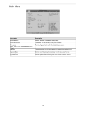
Date when the BIOS setup utility was created. second format. 36 year format. Set the system time following the weekday-month-day- Set the date following the hour-minute- Technical specifications for the installed processor. Main Menu Parameter BIOS Version BIOS Build Date Processor CPU Type CPU Core Frequency CPU Count Memory System Date System Time Description Version number of the BIOS setup utility. Determines how much total memory is present during the POST.
Date when the BIOS setup utility was created. second format. 36 year format. Set the system time following the weekday-month-day- Set the date following the hour-minute- Technical specifications for the installed processor. Main Menu Parameter BIOS Version BIOS Build Date Processor CPU Type CPU Core Frequency CPU Count Memory System Date System Time Description Version number of the BIOS setup utility. Determines how much total memory is present during the POST.

Acer AT110 F2 Service Guide
Page 49
... enabled, This setting will use for the related PCI-E Disabled slot. Enabled Disabled Primary Graphics Select the primary video device that that the Add-On BIOS will initialize the Enabled device expansion ROM for output. PCI Configuration Parameter PERR# Generation Description Enable/Disable PERR Generation.
... enabled, This setting will use for the related PCI-E Disabled slot. Enabled Disabled Primary Graphics Select the primary video device that that the Add-On BIOS will initialize the Enabled device expansion ROM for output. PCI Configuration Parameter PERR# Generation Description Enable/Disable PERR Generation.
Acer AT110 F2 Service Guide
Page 52
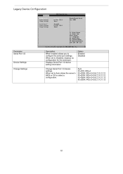
When set to Auto allows the server's BIOS or OS to select a configuration. Option Enabled Disabled Change Settings Auto IO=3F8; Displays Serial Port 1/2 device setting information Change Serial Port 1/2 device settings. IRQ=3,4,5,6,7,10,11,12 IO=3E8h; IRQ=3,4,5,6,7,10,11,12 48 When set to configure the serial port settings. IRQ=3,4,5,6,7,10,11,12 IO=2F8h; Legacy Device Configuration Parameter Serial Port 1/2 Device Settings Description When enabled allows you to Disabled, displays no configuration for the serial port. IRQ=4 IO=3F8h; IRQ=3,4,5,6,7,10,11,12 IO=2E8h;
When set to Auto allows the server's BIOS or OS to select a configuration. Option Enabled Disabled Change Settings Auto IO=3F8; Displays Serial Port 1/2 device setting information Change Serial Port 1/2 device settings. IRQ=3,4,5,6,7,10,11,12 IO=3E8h; IRQ=3,4,5,6,7,10,11,12 48 When set to configure the serial port settings. IRQ=3,4,5,6,7,10,11,12 IO=2F8h; Legacy Device Configuration Parameter Serial Port 1/2 Device Settings Description When enabled allows you to Disabled, displays no configuration for the serial port. IRQ=4 IO=3F8h; IRQ=3,4,5,6,7,10,11,12 IO=2E8h;

Acer AT110 F2 Service Guide
Page 57
...'s access to the Setup menus. To enable or disable this password will be set . Enable or disable Power Button Lockout Enabled Disabled Not Installed Enabled BIOS Write Protect Enable/Disable BIOS Write Protect function. Enabled Disabled Select Enabled to activate TPM support feature.
...'s access to the Setup menus. To enable or disable this password will be set . Enable or disable Power Button Lockout Enabled Disabled Not Installed Enabled BIOS Write Protect Enable/Disable BIOS Write Protect function. Enabled Disabled Select Enabled to activate TPM support feature.
Acer AT110 F2 Service Guide
Page 59
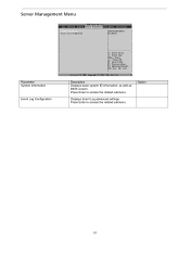
Displays Event Log advanced settings. Server Management Menu Parameter System Information Description Displays basic system ID information, as well as BIOS version. Press Enter to access the related submenu. Option Event Log Configuration 55 Press Enter to access the related submenu.
Displays Event Log advanced settings. Server Management Menu Parameter System Information Description Displays basic system ID information, as well as BIOS version. Press Enter to access the related submenu. Option Event Log Configuration 55 Press Enter to access the related submenu.
Acer AT110 F2 Service Guide
Page 63
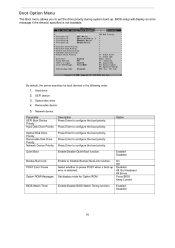
... pause POST when a boot-up . Set display mode for boot devices in the following order: 1. Removable device 5. Option ROM Messages BIOS Watch Timer Enable/Disable BIOS Watch Timing function. 59 Optical disc drive 4. Press Enter to configure the boot priority. Press Enter to configure the boot priority. Enable/Disable... Quiet Boot Description Press Enter to configure the boot priority. Enabled Disabled On Off Disabled All, But Keyboard All Errors Force BIOS Keep Current Enabled Disabled Option Bootup NumLock POST Error Pause Enable or Disable Bootup NumLock function.
... pause POST when a boot-up . Set display mode for boot devices in the following order: 1. Removable device 5. Option ROM Messages BIOS Watch Timer Enable/Disable BIOS Watch Timing function. 59 Optical disc drive 4. Press Enter to configure the boot priority. Press Enter to configure the boot priority. Enable/Disable... Quiet Boot Description Press Enter to configure the boot priority. Enabled Disabled On Off Disabled All, But Keyboard All Errors Force BIOS Keep Current Enabled Disabled Option Bootup NumLock POST Error Pause Enable or Disable Bootup NumLock function.

Acer AT110 F2 Service Guide
Page 64
P3: WDC WD1001FAES-22W7A0 P5: ATAPI DVD D DH16D5SH Press Enter to configure the device as the boot-up drive. Press Enter to configure the device as the boot-up drive. 60 Parameter Built-in EFI Shell Description Press Enter to configure the device as the Option boot-up drive. BIOS setup will display an error message if the drive(s) specified is not bootable. Boot Manager Menu The Boot manager menu allows you to specify the boot-up drive.
P3: WDC WD1001FAES-22W7A0 P5: ATAPI DVD D DH16D5SH Press Enter to configure the device as the boot-up drive. Press Enter to configure the device as the boot-up drive. 60 Parameter Built-in EFI Shell Description Press Enter to configure the device as the Option boot-up drive. BIOS setup will display an error message if the drive(s) specified is not bootable. Boot Manager Menu The Boot manager menu allows you to specify the boot-up drive.
Acer AT110 F2 Service Guide
Page 65
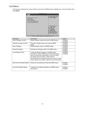
... kinds of the exit options then press Enter. Saves changes made and close the BIOS setup. Discards all changes made and close the BIOS setup. If you are quite demanding in the BIOS setup. Option Enabled Disabled Enabled Disabled Enabled Disabled Enabled Disabled Enabled Disabled Save as ... and Exit Discard Changes and Exit Save Changes Discard Changes Load Default Values Description Saves changes made in the BIOS setup Loads the default settings for all BIOS setup parameters. Exit Menu The Exit menu displays the various options to load these settings, the system might ...
... kinds of the exit options then press Enter. Saves changes made and close the BIOS setup. Discards all changes made and close the BIOS setup. If you are quite demanding in the BIOS setup. Option Enabled Disabled Enabled Disabled Enabled Disabled Enabled Disabled Enabled Disabled Save as ... and Exit Discard Changes and Exit Save Changes Discard Changes Load Default Values Description Saves changes made in the BIOS setup Loads the default settings for all BIOS setup parameters. Exit Menu The Exit menu displays the various options to load these settings, the system might ...
Acer AT110 F2 Service Guide
Page 66
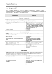
...memory modules in the left column. Diskette/IDE drive connection/cables Diskette/IDE disk drives See "Undetermined Problems". Enter BIOS Setup and Load default settings. Enter BIOS Setup and Load default settings. Hard disk drive cannot format completely. 62 If no check procedure is indicated, ...in power saving mode. Hard disk drive cable. system does not work , then replace a good fan. If directed to Enabled. Enter BIOS Setup and load default settings. Reload software from Recovery CD. With the system power on, measure the voltage of processor fan connector. Troubleshooting ...
...memory modules in the left column. Diskette/IDE drive connection/cables Diskette/IDE disk drives See "Undetermined Problems". Enter BIOS Setup and Load default settings. Enter BIOS Setup and Load default settings. Hard disk drive cannot format completely. 62 If no check procedure is indicated, ...in power saving mode. Hard disk drive cable. system does not work , then replace a good fan. If directed to Enabled. Enter BIOS Setup and load default settings. Reload software from Recovery CD. With the system power on, measure the voltage of processor fan connector. Troubleshooting ...
Acer AT110 F2 Service Guide
Page 67
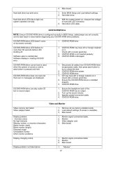
...(if screen is installed properly. Main board. Hard disk drive. CD/DVD-ROM Drive NOTE: Ensure CD/DVD-ROM drive is configured correctly in BIOS Setup, cable/jumper are displayed. 2. 3. 1. 2. 3. CD/DVD-ROM drive CD may have dirt or foreign material on it . Monitor ...Video adapter card Main board Display problem: - Enter BIOS Setup and Load default settings. Remove all cables from CD/DVD-ROM drive except power cable, then press eject button to try to reinstall disc...
...(if screen is installed properly. Main board. Hard disk drive. CD/DVD-ROM Drive NOTE: Ensure CD/DVD-ROM drive is configured correctly in BIOS Setup, cable/jumper are displayed. 2. 3. 1. 2. 3. CD/DVD-ROM drive CD may have dirt or foreign material on it . Monitor ...Video adapter card Main board Display problem: - Enter BIOS Setup and Load default settings. Remove all cables from CD/DVD-ROM drive except power cable, then press eject button to try to reinstall disc...
Acer AT110 F2 Service Guide
Page 68
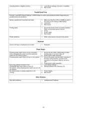
...1. Printing failed. 1. 2. 3. 4. Printer cable. No system power, or power supply fan is properly installed. Printer. Ensure the AC-LINK in BIOS Setup to Stay-off. Load default settings (if screen is not set to OFF. Reload software from electrical outlet can turn on keyboard do not... does not turn off system. (Only unplugging the power cord from Recovery CD. Main board Parallel/Serial Ports Execute "Load BIOS Default Settings" in BIOS Setup of the machine, just above the connector for the printer. Keyboard Power Supply Pressing power switch does not turn off the...
...1. Printing failed. 1. 2. 3. 4. Printer cable. No system power, or power supply fan is properly installed. Printer. Ensure the AC-LINK in BIOS Setup to Stay-off. Load default settings (if screen is not set to OFF. Reload software from electrical outlet can turn on keyboard do not... does not turn off system. (Only unplugging the power cord from Recovery CD. Main board Parallel/Serial Ports Execute "Load BIOS Default Settings" in BIOS Setup of the machine, just above the connector for the printer. Keyboard Power Supply Pressing power switch does not turn off the...

Acer AT110 F2 Service Guide
Page 69
... PPI is not available Platform PCI resource requirements cannot be used to restore the BIOS to a working state. Rename the image file to the bootable hand drive or the bootable floppy diskette. BIOS Beep Codes BIOS Beep Codes Table PEI Beep Codes # of the Architectural Protocols are not available ...not available DXE Beep Codes # of Beeps 1 4 5 5 6 7 8 Description Invalid password Some of Beeps 1 1 2 3 3 4 4 7 Description Memory not Installed. In the event that the BIOS becomes corrupt the boot block can be met BIOS Recovery Instruction AMI has an embedded recovery technique.
... PPI is not available Platform PCI resource requirements cannot be used to restore the BIOS to a working state. Rename the image file to the bootable hand drive or the bootable floppy diskette. BIOS Beep Codes BIOS Beep Codes Table PEI Beep Codes # of the Architectural Protocols are not available ...not available DXE Beep Codes # of Beeps 1 4 5 5 6 7 8 Description Invalid password Some of Beeps 1 1 2 3 3 4 4 7 Description Memory not Installed. In the event that the BIOS becomes corrupt the boot block can be met BIOS Recovery Instruction AMI has an embedded recovery technique.

Acer AT110 F2 Service Guide
Page 71
When recovery process is completed, reset the system. 67 Then system would recover the BIOS image automically. You may see the page as the following figures shows. 5 6 Enter "Proceed with flash update" page, the system would enter BIOS Setup Menu. Recovery Stage 4 Connect the disk, here we use FAT disk and set recovery jumper.
When recovery process is completed, reset the system. 67 Then system would recover the BIOS image automically. You may see the page as the following figures shows. 5 6 Enter "Proceed with flash update" page, the system would enter BIOS Setup Menu. Recovery Stage 4 Connect the disk, here we use FAT disk and set recovery jumper.

Acer AT110 F2 Service Guide
Page 72
...) Pre-memory South Bridge initialization (South Bridge module specific) OEM pre-memory initialization codes Memory initialization. SPD reading has failed Memory initialization error. BIOS POST Error Messages List BIOS POST error message list PEI Phase Status Code Progress Code 0x10 0x11 0x12 0x13 0x14 0x15 0x16 0x17 0x18 0x19 0x1A 0x1B 0x1C...
...) Pre-memory South Bridge initialization (South Bridge module specific) OEM pre-memory initialization codes Memory initialization. SPD reading has failed Memory initialization error. BIOS POST Error Messages List BIOS POST error message list PEI Phase Status Code Progress Code 0x10 0x11 0x12 0x13 0x14 0x15 0x16 0x17 0x18 0x19 0x1A 0x1B 0x1C...


